EasyManua.ls Logo

Siemens LEC1 Series User Manual

Siemens LEC1 Series
17 pages
To Next Page IconTo Next Page
Page #1 background imageLoading...
Page #1 background image
CC1N7761en
19.02.2007
Building Technologies
HVAC Products
7
761
Control Units
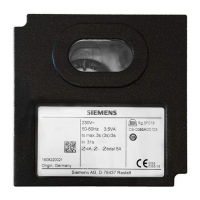
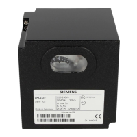
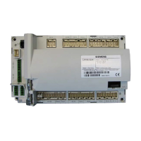
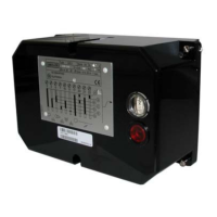
LEC1...
Control unit for double- or multiflame supervision of oil, gas or forced draft oil /
gas burners of any fuel throughput, suited for continuous or intermittent opera-
tion.
The LEC1... and this Data Sheet are intended for use by OEMs which integrate the
control units in their products!
Use
The LEC1... is designed for the fully automatic startup and supervision of forced draft
oil or gas burners where flame supervision should or must be carried out by separate
flame safeguards, e.g. with:
Double supervision of the main flame or pilot and main flame by 2 identical or dif-
ferent detectors
Supervision of forced draft oil / gas burners with different types of detectors, de-
pending on the selected operating mode
Multiflame supervision, that is, central and simultaneous control of the startup and
supervision sequence of several burners the flames of which must be individually
supervised by 1 or 2 flame safeguards each
Supplementary Data Sheets
LAE10 Data Sheet N7781
LFE10 Data Sheet N7781
LFE50 Data Sheet N7783
Question and Answer IconNeed help?

Do you have a question about the Siemens LEC1 Series and is the answer not in the manual?

Siemens LEC1 Series Specifications

General IconGeneral
Supply voltage24 V DC
Digital output current0.5 A
Protection classIP20
Current Consumption100 mA
Storage Temperature-25°C to +70°C

Summary

Control Units

Use

Describes the application and intended use of the control unit.

Special features

Details the specific capabilities and functions of the LEC1... control unit.

Safety and Installation Notes

Warning notes

Highlights crucial safety precautions to avoid injury and damage.

Mounting and Installation Notes

Provides guidelines for unit installation and electrical connection.

Technical Specifications and Compliance

Electrical connection of flame detectors

Details electrical connection requirements for flame detectors.

Commissioning notes

Lists key checks to perform during the unit's initial setup and operation.

Standards and certificates

Lists relevant compliance standards and certifications for the product.

Product Information

Disposal notes

Provides guidance on the environmentally responsible disposal of the unit.

Mechanical design

Describes the physical construction and materials of the control unit.

Type summary and ordering

Provides an overview of different unit types and their ordering information.

Accessories

Lists optional or required accessories for the control unit.

Technical Data

General unit data

Specifies the core electrical and physical characteristics of the unit.

Environmental conditions

Details the operating and storage environmental parameters for the unit.

Flame supervision

Explains the flame supervision capabilities and related components.

Functionality and Operation

Prerequisites for burner startup

Lists the conditions that must be met before the burner can start.

Startup sequence

Describes the step-by-step process of the burner's startup sequence.

Program Indicator

Reading the program indicator

Explains how to interpret the status displayed by the program indicator.

Adjustment Facilities

Adjusting preignition and prepurge times

Details setting preignition and prepurge times on the unit.

Safety Time Adjustments

Covers the adjustment of ignition, 1st, and 2nd safety times.

Basic Diagram

Basic Diagram Overview

Presents the fundamental electrical schematic of the LEC1 control unit.

Programming Mechanism

Sequence diagram of programming mechanism

Illustrates the operational flow of the programming mechanism.

Switching times

Lists and defines the various timing parameters for the programming mechanism.

Legend for Sequence Diagrams

Provides a key to understand symbols used in sequence diagrams.

Connection Examples

Oil Burner Supervision

Shows connection examples for oil burner supervision.

Air Damper Control Sequence

Illustrates the detailed control sequence for the air damper.

Gas Burner Supervision

Shows connection examples for gas burner supervision.

Selectable Oil/Gas Burner Operation

Illustrates connection examples for selectable oil/gas burner operation.

Modulating Burner Supervision

Details connections for supervising modulating burners.

Semiautomatic Operating Mode

Explains the control circuit for semiautomatic burner operation.

Dimensions

Legend for Dimension Diagrams

Key to symbols used in the dimension diagrams.

Related product manuals