53 Siemens Industry, Inc.
RTU Programming and Scripting - Details
This section is intended for the programmer of the RTU or host system and includes
details about meter and element addressing, register locations, data formats and
protocol examples.
Register Organization
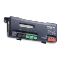
The MD-xxHD meter communicates through the reading and writing of registers. Registers are organized
into functional groups and are compliant with the SunSpec Modbus interface model.
▪ SunSpec Common Registers
▪ SunSpec TCP Network Stack Registers
▪ SunSpec Serial Interface Registers
▪ SunSpec Energy Meter
▪ DENT Factory Registers
▪ DENT User Command Registers
▪ DENT User Configuration Registers
▪ DENT Metrology Registers
▪ DENT Waveform Capture Registers
The complete register set is included as an Excel file on the supplied thumb drive or at:
https://www.dentinstruments.com/siemens
Element vs. System Scope
Element
The term “element” is used in two contexts. Physically, the term Element is used to describe
groups of three channel sections identified by alphabetic letter on the silk screen of the PCBA
(such as A,B,C,D). In a three-phase power system these correspond to electric circuits.
Logically the term Element describes the scope of a data item, register or point (Modbus
register or BACnet object). Each Element based point is accessed by choosing the appropriate
Modbus address, BACnet object range, or BACnet structured view. Elements in turn have points
that refer to individual channels or to SUMS or AVERAGES of those channels. Registers that
contain data inclusive of more than one channel are identified as being either SUMS or
AVERAGES of the enabled channels within an element. In a BACnet structured view an
Element represents a level of organization for related points.
Channel
Channels are identified on the circuit board as CH1, CH2, or CH3 and represent physical CT inputs. In
three phase system configurations, these correspond to a current load on a corresponding line voltage. In
single phase configurations, they are just used to identify a CT location. Registers providing data for an
individual channel are also described as elements in their scope as a unique value exists for each Slave
Address or BACnet object instance.

 Loading...
