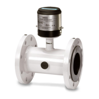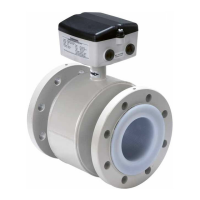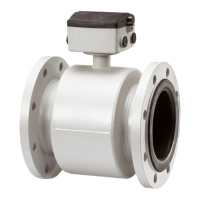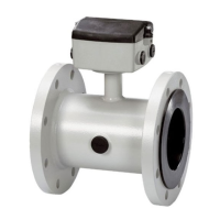
Do you have a question about the Siemens SITRANS F MAG 6000 I and is the answer not in the manual?
| Measurement Principle | Electromagnetic |
|---|---|
| Process Pressure | Up to 40 bar |
| Conductivity | ≥ 5 μS/cm |
| Repeatability | \u00b10.1% of reading |
| Ambient Temperature | -20 to +60 °C |
| Power Supply | 24 V DC |
| Output Signal | 4 to 20 mA, HART |
| Lining Material | PTFE, rubber |
| Electrode Material | Stainless steel, platinum |
| Protection Degree | IP67 |
| Material | Stainless steel |
| Nominal Diameter | DN 15 to DN 2000 |
| Accuracy | ±0.2% of flow rate (optional: ±0.1% of flow rate) |
General introduction and target audience for the manual.
Lists all components included with the device.
Information on document revision and feedback.
Details on how to identify the device and its versions.
Provides links and resources for additional product information.
Important safety precautions for handling and operating the device.
Compliance with national regulations and safety standards.
Safety guidelines for installing the device in hazardous environments.
Details on the ATEX certification for hazardous areas.
Information on FM/CSA certification for hazardous locations.
FM/CSA certification details for specific hazardous area classifications.
Information on obtaining device certification documents.
Overview of sectors and industries where the flowmeter is used.
Lists the main parts of the SITRANS F M flowmeter system.
Describes the physical design and features of the transmitter.
Highlights key features like SENSORPROM®, communication modules, and output options.
Explains the electromagnetic induction principle behind the flowmeter's operation.
Crucial safety measures before and during installation.
Guidelines for suitable environmental and positional installation.
Instructions for installing the flowmeter in its compact configuration.
Steps for installing the transmitter separately from the sensor.
How to mount the transmitter on a wall using a standard plate.
Instructions for mounting using an assembly bracket on pipes or walls.
Essential safety measures for electrical connections.
Detailed wiring diagrams and instructions for connecting the device.
Steps to connect the sensor to the remote transmitter.
Specific wiring requirements for hazardous area installations.
How to connect optional communication modules.
Steps for correctly reassembling the device after maintenance.
How to operate the device using its local display and keypad.
Explanation of the device's menu hierarchy and navigation.
Procedure for changing the device's access password.
Guide to modifying fundamental device parameters.
How to customize the operator menu for daily use.
Instructions for changing the display language.
Overview of the transmitter's functions and menu diagrams.
Configuration options for current, digital, and relay outputs.
Using external signals to control device functions like batch and totalizers.
Information about sensor calibration, size, and factors.
How to reset totalizers or restore factory settings.
Accessing service and diagnostic functions.
Explanation of the error and status log system.
A comprehensive list of error codes, their causes, and remedies.
Routine inspection and maintenance procedures for the device.
Guidelines for device repair, noting it must be by authorized personnel.
How to contact Siemens for technical assistance and support resources.
Steps and required forms for returning the device for service.
A guide to diagnosing and resolving common issues based on symptoms.
A systematic checklist for verifying transmitter operation and identifying faults.
Detailed technical specifications for the device's operation and performance.
Physical dimensions and weight of the transmitter unit.
Information regarding the flowmeter's measurement accuracy and reference conditions.
Details on how the output signals behave under different conditions.
Information and descriptions of cables used with the flowmeter.
Specifications and requirements for cables used for connection.
Information on how to order spare parts and accessories.
Lists available accessories like mounting brackets and communication modules.
Lists common spare parts for the device, like display units and covers.
A general overview of the transmitter's menu structure.
Menu diagram detailing how to configure basic device settings.
Menu diagram for configuring current output parameters.
Menu diagram for digital output pulse configuration.
Menu diagram for digital output frequency configuration.
Menu diagram for setting error levels.
Menu diagram for viewing and managing error numbers.
Menu diagram for setting flow direction and limit switches.
Menu diagram for configuring batch processing functions.
Menu diagram for configuring external input signals.
Menu diagram for sensor-related settings and information.
Menu diagram for resetting device parameters and totalizers.
Menu diagram for accessing service and diagnostic functions.
Menu diagram for customizing the operator interface.
Menu diagram showing how to view product identification details.
Menu diagram for configuring communication modules.
Table detailing default factory settings for various parameters.
Table of Qmax settings based on dimension for 50 Hz.
Table of settings dependent on dimension for 60 Hz.
Batch and pulse output settings based on dimension for 50 Hz.
Batch and pulse output settings based on dimension for 60 Hz.
Provides wiring diagrams and installation schematics for the device.


