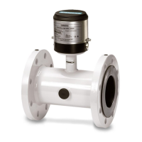
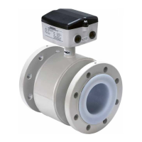
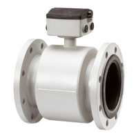
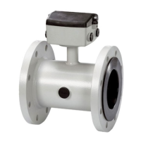
MAG 6000 I / MAG 6000 I Ex de transmitter
Operating Instructions, 04/2016, A5E02083319-AG
61
Technical specifications for MAG 6000 I standard and Ex version
Mode of operation and design
Electromagnetic with pulsed constant field
Empty pipe Detection of empty pipe (special cable re-
quired in remote mounted installation)
Excitation frequency Depends on sensor size
Electrode input impedance
14
11 to 30 V DC, R
i
= 4.4 kΩ
Activation time 50 ms
I
11 V DC
= 2.5 mA, I
30 V DC
= 7 mA
0 to 20 mA (active/passive)
R
max
500 Ω @ V
max
30 V DC
Passive current output R
min
0 Ω @ V
min
12 V DC
R
max
500 Ω @ V
max
30 V DC
Frequency 0 to 10 kHz, 50% duty cycle
Pulse (passive) 3 to 30 V DC, max. 110 mA (Ex version:
max. 30 mA), 200 Ω ≤ R
i
≤10 kΩ (powered
from connected equipment)
Changeover relay, same as current output
0 ... 9.9% of maximum flow
All inputs and outputs are galvanically isolated PELV circuits with 60 VDC isolation
from each other and ground. Exceptions are sensor connections that are connected
Max. measuring error
(incl. sensor and zero point)
MAG 6000 I/MAG 6000 I Ex de ±0.2% ± 1 mm/s
1)
Rated operation conditions

 Loading...


