6. SYSTEM PARAMETERS English
Parameter Function Range
[Default]
Description / Notes
© Siemens plc 1999 G85139-H1751-U529-D1
51
4/8/9
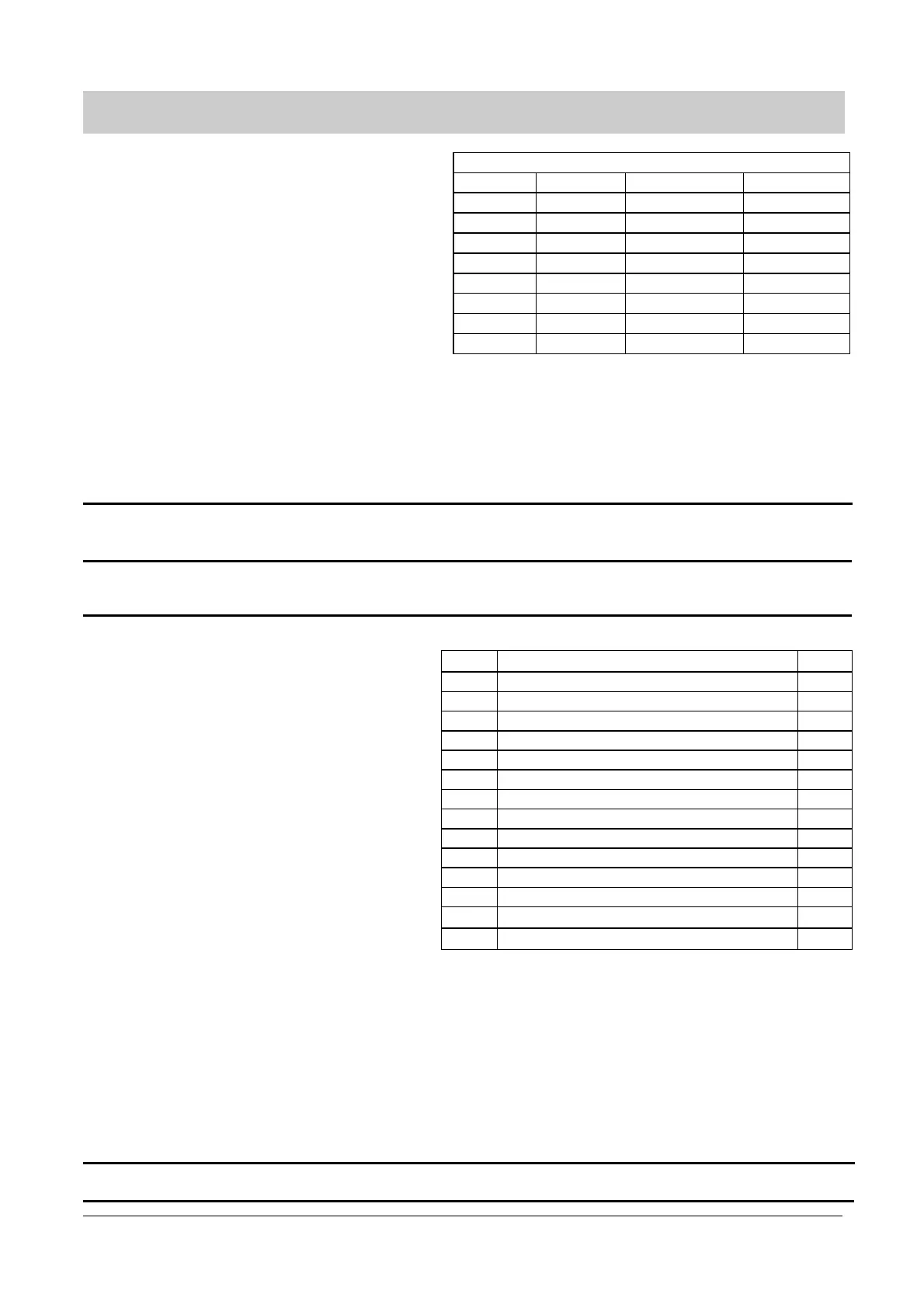
Binary Coded Fixed Frequency Mapping
DIN3
P053
DIN4
P054
DIN5
P055
FF5
P046
00 0
FF6
P047
00 1
FF7
P048
01 0
FF8
P049
01 1
FF1
P041
10 0
FF2
P042
10 1
FF3
P043
11 0
FF4
P044
11 1
Note: If P051 or P052 = 6 or 18 while P053 or P054 or P055 = 17
then the setpoints are added.
Examples: (1) P053 = 17, P054 = 17, P055 = 17:
All 8 fixed frequencies are available
e.g. DIN3 = 1, DIN4 = 1, DIN5 = 0 Þ FF3 (P043)
(2) P053 ¹ 17, P054 = 17, P055 = 17:
DIN3 is fixed at zero (only FF5 to FF8 available)
e.g. DIN4 = 1, DIN5 = 0 Þ FF7 (P048)
P056
Digital input debounce time 0 - 2
[0]
0 = 12.5 ms
1 = 7.5 ms
2 = 2.5 ms
P057
Digital Input Watchdog Trip
(seconds)
0.0-650.0
[1.0]
Time interval between expected ‘Watchdog kicks’ or if this time interval should
lapse without a pulse on one of the digital inputs, an F057 trip will occur.
(See P051 to P055 and P356)
P061
Selection relay output RL1 0 - 13
[6]
Sets the relay function, output RL1 (terminals 18,19 and 20)
Value Relay function Active
3
0 No function assigned (relay not active) Low
1 Inverter is running High
2 Inverter frequency 0.0 Hz Low
3 Motor running direction right High
4 External brake on (see parameters P063/P064) Low
5 Inverter frequency greater than minimum frequency High
6 Fault indication
1
Low
7 Inverter frequency greater than or equal to setpoint High
8 Warning active
2
Low
9 Output current greater than or equal to P065 High
10 Motor current limit (warning)
2
Low
11 Motor over temperature (warning)
2
Low
12 PID closed loop motor LOW speed limit High
13 PID closed loop motor HIGH speed limit High
1
Inverter switches off (see parameter P930 and P140 to P143 and section 7).
2
Inverter does not trip(see parameter P931).
3
‘Active low’ = relay OFF/ de-energised or ‘Active high’ = relay ON/
energised
Note: If the external brake function is used (P061 or P062 = 4)
and additional slip compensation is used (P071¹ 0),
minimum frequency must be less than 5 Hz (P012 < 5.00),
otherwise the inverter may not switch off.
Warning:Relay operation is not defined during parameter changes and
may change unpredictably.
Ensure any equipment connected to the relays will remain safe
if the relays change state during parameterisation.
P062 Selection relay output RL2. 0 - 13
[8]
Sets the relay function, output RL2 (terminals 21and 22) (refer to the table in
P061).