English 6. SYSTEM PARAMETERS
Parameter Function Range
[Default]
Description / Notes
G85139-H1751-U529-D1 © Siemens plc 199
4/8/99
52
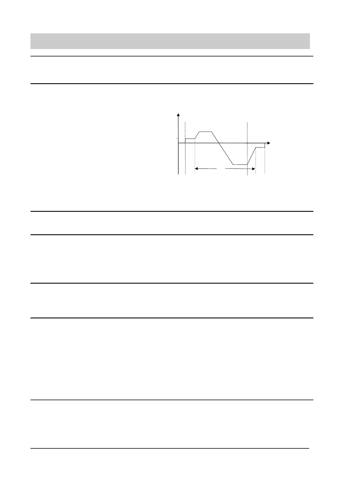
P063
External brake release delay
(seconds)
0 - 20.0
[1.0]
Only effective if the relay output is set to control an external brake
(P061 or P062 = 4). In this case when the inverter is switched on, it will run at
the minimum frequency for the time set by this parameter before releasing the
brake control relay and ramping up (see illustration in P064).
P064
External brake stopping time
(seconds)
0 - 20.0
[1.0]
As P063, only effective if the relay output is set to control an external brake.
This defines the period for which the inverter continues to run at the minimum
frequency after ramping down and while the external brake is applied.
Notes: (1) Settings for P063 and P064 should be slightly longer than the
actual time taken for the external brake to apply and release
respectively
(2) Setting P063 or P064 to too high a value, especially with
P012 set to a high value, can cause an overcurrent warning or
trip as the inverter attempts to turn a locked motor shaft.
P065
Current threshold for relay (A) 0.0-300.0
[1.0]
This parameter is used when P061 or P062 = 9. The relay switches on when
the motor current is greater than the value of P065 and switches off when the
current falls to 90% of the value of P065 (hysteresis).
P066
Compound braking 0 - 250
[0]
0 = Off
1 to 250 = Defines the level of DC superimposed on the AC waveform,
expressed as a percentage of P083. Generally, increasing this value
improves braking performance, however, with 400V inverters, a high
value in this parameter could cause F001 trips.
Note: Compound braking does not operate in Sensorless Vector control mode
(P077=3).
P069
Ramp extension disable
0 - 1
[1]
0 - Ramp extension disabled.
1 - Ramp extension enabled. Ramp time is increased during current limit,
overvoltage limit and slip limit to prevent tripping.
Note: Ramp extension does not occur when in vector control (P077=3).
P070
Braking Resistor Duty Cycle (MMV
only)
0 - 4
[0]
0 =5%
1 = 10%
2 = 20%
3 = 50%
4 = 100% (i.e. continuous)
WARNING: Standard braking resistors for the MICROMASTER Vector
are designed for the 5% duty cycle only. Do not select
higher duty cycles unless suitably rated resistors are
being used to handle the increased power dissipation.
The maixmum on time for values 0 to 3 is limited
according to the brake resistor thermal capacity. Limit is
12 seconds for 5%, increasing to 25 seconds for 50%.
ON OFF
P063
A
P064
A
f
min
B
t
A = Brake applied
B = Brake removed