26/09/97
24
P022 •
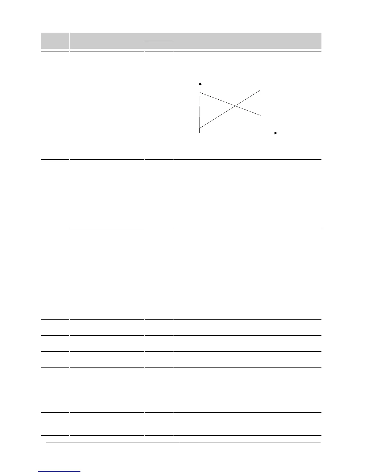
Maximum analogue frequency
(Hz)
0 - 400.00
[50.00]
Frequency corresponding to the highest analogue input value, i.e.
10 V, determined by P023. This can be set to a lower value than P021
to give an inverse relationship between analogue input and frequency
output.
i.e.
Note: The output frequency is limited by values entered for
P012/P013.
P023 •
Analogue input function 0 - 2
[0]
0 = 0 V to 10 V
1 = 2 V to 10 V
2 = 2 V* to 10 V
* The inverter will come to a controlled stop if V < 1 V.
WARNING: The motor can automatically run without a
potentiometer or voltage source connected between
pins 3 and 4.
WARNING: With P023=2, the inverter will automatically start
when V goes above 1 V. This equally applies to
analogue and digital control (i.e. P006 = 0 or 1).
P024 •
Analogue setpoint addition 0 - 2
[0]
If the inverter is not in analogue mode (P006 = 0 or 2), setting this
parameter to ‘1’ causes the analogue input value to be added.
0 = No addition.
1 = Addition of the analogue setpoint (defined by P023) to the
fixed frequency or the motor potentiometer frequency.
2 = Scaling of digital/fixed setpoint by analogue input (P023) in
the range 0 - 100%.
Note: By selecting a combination of reversed negative fixed
frequency settings and analogue setpoint addition, it is
possible to configure the inverter for ‘centre zero’ operation
with a +/-5 V supply or a 0 - 10 V potentiometer so that the
output frequency can be 0 Hz at any position, including the
centre position.
P027 •
Skip frequency 2 (Hz) 0 - 400.00
[0.00]
See P014.
P028 •
Skip frequency 3 (Hz) 0 - 400.00
[0.00]
See P014.
P029 •
Skip frequency 4 (Hz) 0 - 400.00
[0.00]
See P014.
P031 •
Jog frequency right (Hz) 0 - 400.00
[5.00]
Jogging is used to advance the motor by small amounts. It is controlled
via the JOG button or with a non-latching switch on one of the digital
inputs (P051 to P053).
If jog right is enabled (DINn = 7), this parameter controls the frequency
at which the inverter will run when the switch is closed. Unlike other
setpoints, it can be set lower than the minimum frequency.
P032 •
Jog frequency left (Hz) 0 - 400.00
[5.00]
If jog left is enabled (DINn = 8), this parameter controls the frequency
at which the inverter will run when the switch is closed. Unlike other
setpoints, it can be set lower than the minimum frequency.
f
V
P021
P021
P022
P022