Service Instructions
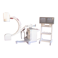
Multimobil 5C
Siemens Ltd. Med India Version 5.0
Page 22 of 73
Copyright © SIEMENS LTD. All rights reserved. For internal use only
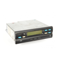
5.1.3 Checking the LED’s
Switch the Unit ON.
After the initialisation, the default data 60 kV and 10 mAs are displayed at first time
switch ON or last stored kV & mAs value.
Check for the following LED’s
Mode PCB LED Purpose
V3 Mains ON
V9 Mains ON
V12 24V for relay
D 506
V25 Filament power
supply 15 / 24 V
Standby Mode
D508 V11 5V for collimator
Preparation Mode D915 V22 Preparation ON
Exposure Mode D915 V23 Exposure ON
Error D915 V24 Error Indication
5.2 Checking the Control Voltages
When the unit is ON, relays K2 on D506 is ON.
SMPS placed in the Inverter module gets supply, Measure the voltages DC at X15
connector of D915 PCB.
Pin
no.
Signal name Input/output
w.r.t. D915
Max. Permissible
voltage/current
1 Dgnd Input 0 V
2 NC NC -
3 Dgnd Input 0 V
4 DC supply Input +5 V
5 DC supply Input +15 V
6 Agnd Input 0 V
7 DC supply Input -15 V
-nc- = No Connection
 Loading...