Service Instructions
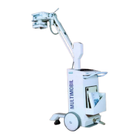
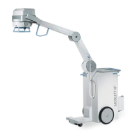
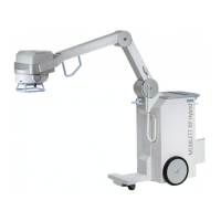
Multimobil 5C
Siemens Ltd. Med India Version 5.0
Page 3 of 73
Copyright © SIEMENS LTD. All rights reserved. For internal use only
5.3.2 Checking the Filament frequency ...................................................................................... 24
5.3.3 Filament current measurement .......................................................................................... 24
5.3.4 Checking of kV and mAs values ........................................................................................ 24
5.4 AUTOMATIC DOSAGE REGULATION ............................................................................................ 26
5.4.1 ADR Stop Mode (Manual).................................................................................................. 26
5.5 REPLACING THE SINGLE TANK.................................................................................................... 27
5.5.1 Replacing the collimator..................................................................................................... 27
5.5.2 Aligning the X-ray field to Image Intensifier ....................................................................... 27
6 CCU AND CAMERA CONTROL ............................................................................................... 29
6.1 INTRODUCTION....................................................................................................................29
6.2 RATINGS................................................................................................................................ 29
6.3 CONNECTION TERMINALS OF CAMERA CONTROL UNIT (CCU) .................................... 30
6.4 PERFORMANCES /FUNCTIONS .......................................................................................... 30
6.5 ADJUSTMENTS & EXTERNAL CONTROL ........................................................................... 34
6.6 OSD PARAMETERS SETTINGS ................................................................................................... 37
6.7 PIN ASSIGNMENT ...................................................................................................................... 42
6.7.1 Pin assignment & interfacing details.................................................................................. 43
6.8 PERIODIC CHECKS.................................................................................................................... 43
7 MECHANICAL CHECKS AND ADJUSTMENTS ...................................................................... 44
7.1 PARTS WHICH NEEDS PERIODIC ADJUSTMENTS ........................................................................... 44
7.1.1 BRAKES............................................................................................................................. 44
7.1.2 BEARINGS......................................................................................................................... 45
7.1.3 V-BELT............................................................................................................................... 46
7.1.4 CHAIN ................................................................................................................................ 46
7.2 PARTS WHICH NEEDS SERVICING OR REPLACEMENTS.................................................................. 47
7.2.1 V-Belt ................................................................................................................................. 47
7.2.2 Bearings ............................................................................................................................. 47
7.2.3 Brake liners ........................................................................................................................ 48
7.3 TROUBLE SHOOTING AND RECTIFICATION ................................................................................... 48
8 APPENDIX I ............................................................................................................................... 50
8.1 SPECIFIC ERROR CODE HANDLING ............................................................................................ 50
8.1.1 Unit not turning ON ............................................................................................................ 50
8.1.2 No X-ray ............................................................................................................................. 51
8.1.3 No Standby ........................................................................................................................ 53
8.2 INITIALISATION ERROR CODES ................................................................................................... 54
8.2.1 CodE 90 (EPROM CHECKSUM FAILURE) ..................................................................... 54
8.2.2 CodE 96 (KV SOLL FAILURE) ......................................................................................... 54
8.2.3 CodE 97 ( mA FAILURE) .................................................................................................. 54
8.2.4 CodE 99 (LAST RESET BY WATCH DOG TIMER) ......................................................... 54
8.3 STANDBY ERROR CODES........................................................................................................... 55
8.3.1 CodE 02 : +15 V Supply Error ........................................................................................... 55
8.3.2 CodE 03 & 04 : Iheiz < Istby & Iheiz > Istby ...................................................................... 56
8.3.3 CodE 05 : kVist <> 0 .......................................................................................................... 59
8.3.4 CodE 06 : JR <> 0 ............................................................................................................. 60
8.3.5 CodE 33 : Main Inverter Short Circuit................................................................................ 61
8.4 EXPOSURE ERROR CODES................................................................................................ 62
8.4.1 CodE 11 : Main Inverter Short Circuit................................................................................ 62
8.4.2 CodE 12 : kVist > kVmax ................................................................................................... 63
8.4.3 CodE 13 : Iheiz > Imax OR JR > Jrmax............................................................................ 64
8.4.4 CodE 14 : kVist < kVsoll .................................................................................................... 65
8.4.5 CodE 15 : JR < JRS........................................................................................................... 66
8.4.6 CodE 17 : Exposure terminated by Backup Timer ............................................................ 67
8.4.7 CodE 18 : Premature termination of Exposure .................................................................. 68
 Loading...