EasyManua.ls Logo

Siemens MXG461B Series - User Manual

Siemens MXG461B Series
11 pages
Print Icon
To Next Page IconTo Next Page
Loading...
MXG461B Series
Technical Instructions
Document No. 125-4461
May 3, 2006
Modulating Control Valves with
Magnetic Actuators, Positioning
Control and Position Feedback for
Domestic Water
Description
Control valves with magnetic actuators, for modulating control of domestic water, cold
water and hot water systems.
Features
Fast positioning time (< 2 seconds)
Selectable valve characteristic: Equal percentage or linear
Selectable standard interface: 0/2 to 10 Vdc or 0/4 to 20 mA
High resolution (>1:1000)
High rangeability
Wear-free inductive stroke measurement
Spring return A AB closed when de-energized
Positioning control and position feedback signal
Low-friction, heavy-duty and maintenance-free
Phase-cut signal input for Staefa controllers
Product Numbers
See Table 1.
Warning/Caution
Notations
WARNING:
Personal injury or loss of life may occur if you do not
follow the procedures as specified.
CAUTION:
Equipment damage or loss of data may occur if you
do not follow the procedures as specified.
Application
The MX4G61B Series valves are through-port or mixing valves with magnetic
actuators. The actuator is equipped with an electronics module for positioning control
and position feedback. If the power is off, the valve control path A AB is closed.
The short positioning time, high resolution and high rangeability make these valves
ideal for modulating control of domestic, hot and cold water systems.
Siemens Building Technologies, Inc.
Question and Answer IconNeed help?

Do you have a question about the Siemens MXG461B Series and is the answer not in the manual?

Summary

MXG461 B Series Modulating Control Valves

Product Overview and Features

Control valves for modulating domestic water, listing key features like fast positioning and selectable characteristics.

Product Identification and Safety

Presents product numbers and crucial safety warnings/cautions for users.

Application Details

Details the use of MXG461B Series valves in domestic, hot, and cold water systems.

Ordering and Technical Information

Ordering and Accessories

Instructions for ordering valves and stem heaters, plus available replacement parts.

Technical and Automatic Control

Explains the electronic control module and how automatic control ensures precise valve positioning.

Control and Operation

Valve Control and Wiring

Describes actuator control via voltage/current signals and the importance of a 4-wire connection.

Operating State Indicators

Explains LED indications for normal operation, calibration, manual control, and fault conditions.

Manual Operation and Configuration

Manual Operation and Calibration

Details manual adjustment of the valve and the procedure for recalibrating the electronics module.

DIP Switch Configuration

Explains how to configure input signals and valve characteristics using DIP switches.

Control Inputs and Signal Logic

Forced Control and Signal Priority

Describes forced control inputs (terminal Z) and the priority order of control signals.

Installation and Mounting

Valve Characteristics and Installation

Presents valve sizing graphs and provides installation notes, including sealing and straight-through use.

Mounting Position Guidelines

Specifies acceptable mounting positions for the valve, advising against downward orientation.

Component Specifications

Stem Heater and Specifications

Details the Z366 stem heater connection and provides comprehensive technical specifications.

Material, Connections, and Approvals

Materials, Connections, and Approvals

Covers valve materials, pipe/electrical connections, ambient conditions, and agency approvals.

Connection Terminals and Wiring Diagram

Illustrates terminal connections for various controllers and emphasizes 4-wire connection for DC power.

Advanced Wiring Configurations

Phase-Cut Signal Connections

Shows specific terminal connections for controllers utilizing phase-cut signals (0-20 Vdc).

Application Examples and Service

Application Examples and Service

Provides schematic examples of valve applications and guidelines for service and maintenance.

Product Dimensions

Valve Dimensions

Presents a detailed table of dimensions for each MXG461B product number.

Overview

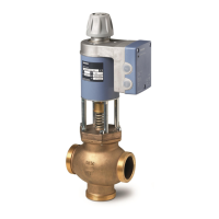
The Siemens MXG461B Series are modulating control valves equipped with magnetic actuators, designed for precise positioning control and offering position feedback. These valves are suitable for domestic, cold, and hot water systems.

Function Description

The MXG461B Series valves are through-port or mixing valves that utilize magnetic actuators for modulating control. The actuator incorporates an electronics module for positioning control and position feedback. In the event of a power failure, the valve's control path A → AB automatically closes due to a spring return mechanism.

The electronics module converts a positioning signal into a phase-cut power signal, which generates a magnetic field within the coil. This magnetic field, in conjunction with counterspring and hydraulic forces, causes the armature to change its position. The armature responds rapidly to signal changes, directly transferring the movement to the valve plug, enabling quick and accurate corrections to load changes.

The valve's position is continuously measured. An internal positioning controller rapidly corrects any system disturbances, ensuring that the positioning signal and the valve stroke are exactly proportional. This controller also provides the position feedback signal.

The magnetic actuator can be driven by any controller providing a 0/2 to 10 Vdc or 0/4 to 20 mA output signal. For optimal control performance, a four-wire connection is recommended. The controller's signal ground terminal (M) must be connected to the valve's terminal M. Terminals M and G0 share the same potential and are internally interconnected within the valve's electronics.

Important Technical Specifications

  • Control Signal Input: 0/2 to 10 Vdc or 0/4 to 20 mA, or 0 to 20 Vdc Phase-cut.
    • Impedance: 100K ohm//5nF for voltage, 240 ohm//5nF for current.
  • Position Feedback Signal Output: 0/2 to 10 Vdc (load resistance > 500Ω) or 0/4 to 20 mA (load resistance < 500Ω).
  • Power Supply:
    • Operating Voltage (AC): 24 Vac +15/-10%, 45 to 65 Hz.
    • Operating Voltage (DC): 20 to 30 Vdc.
    • Nominal Apparent Power (SNA): Varies by model (33 VA to 65 VA).
    • Average True Power (Pmed): Varies by model (15 W to 22 W).
    • Standby Power: <1 W (valve fully closed).
    • Suitable Fuse: Slow, varies by model (3.15 A to 6.3 A).
  • Performance:
    • Positioning Time: <2 seconds.
    • Resolution: >1:1000 (H = Stroke).
    • Rangeability: High.
    • Selectable Valve Characteristic: Equal percentage or linear.
    • High resolution (>1:1000).
    • Wear-free inductive stroke measurement.
  • Valve Data:
    • Nominal Pressure: ANSI 125 (PN 16), 232 psi (16 bar).
    • Operating Pressure (pemax): Varies by model (up to 145 psi).
    • Pressure Differential (Apymax): Varies by model (up to 70 psi).
    • Leakage: A → AB Maximum 0.05% Cv; B → AB Depends on application data (0.2% Cv).
    • Water Temperature: -4°F to 248°F (-20°C to 120°C).
    • Position when de-energized: A → AB closed (spring return).
    • Orientation: Upright to horizontal.
  • Materials:
    • Valve Body, Cover Flange: Red bronze.
    • Seat/Inner Valve: Stainless Steel.
    • Valve Stem Seal: EPDM (O-ring).
    • Screwed Fittings: Bronze/brass.
  • Electrical Connections:
    • Cable Entries: 3 x M20 × 1.5 or PG13.5/G1/2.
    • Connection Terminals: Screw terminals for up to 12 AWG wires.
    • Min. Cross-sectional Area: 0.75 mm².
  • Ambient Conditions:
    • Operation and Storage Temperature: 23°F to 113°F (-5°C to 45°C).
    • Transport Temperature: -13°F to 158°F (-25°C to 70°C).
    • Humidity: 5 to 95% rh (non-condensing).
    • Degree of Protection: IP31 to IEC 529.
  • Dimensions: Varies by model, refer to Figure 18 for detailed measurements.
  • Accessories: Z366 Stem heater for 24 Vac/10W (required for medium temperatures <32°F (0°C)), ASE12 Replacement Circuit Board.

Usage Features

  • Manual Adjustment: The hand wheel allows for mechanical opening of control path A → AB to between 80% and 90% (clockwise) or closing the valve (counterclockwise). When the hand wheel is pressed and turned, forced control signals, input signals, or phase-cut signals are overridden. For automatic control, the hand wheel must be set to the Auto position.
  • Calibration: If the electronics module is replaced or the actuator is turned 180°, the valve's electronics must be recalibrated. This involves setting the hand wheel to Auto and bridging contacts behind a slot on the printed circuit board with a screwdriver. The valve will then travel its full stroke to store end positions. The green LED flashes during calibration (approx. 10 seconds).
  • DIP Switches: Configuration DIP switches allow selection of voltage/current input, correcting span for terminals Y and U, and valve characteristic (equal percentage or linear).
  • Forced Control Input (Z-mode): Terminal Z enables forced control. If Z is not connected, the valve follows the Y-signal or phase-cut signal. Connecting Z to G fully opens the valve, while connecting Z to G0 fully closes it.
  • Signal Priority: The valve prioritizes control signals in the following order: Hand wheel position (Man or Off), Forced control signal Z, Phase-cut signal, and finally, Signal input Y.
  • Mounting Position: Vertical to horizontal mounting is acceptable. The valve should not be mounted below the horizontal.
  • Stem Heater (Z366): The Z366 stem heater is designed for a 24 Vac power supply and is required for applications where medium temperatures fall below 32°F (0°C) to prevent condensation.
  • Straight-through Applications: Only three-way valves are supplied. They can be used as straight-through valves by closing off port B with the supplied accessories (nut, cover, and gasket).
  • Safety: Always disconnect power before fitting or removing the terminal housing. The terminal housing is factory-calibrated and matched to the actuator; replacement should only be done by qualified personnel. Use a four-wire connection with DC power supply. If the controller and valve receive power from separate sources, the valve transformer must not be grounded on the secondary side.

Maintenance Features

  • Low-friction and Robust Design: The valve's design ensures regular servicing is unnecessary and provides a long service life.
  • Maintenance-free Gland: The valve stem is sealed from external influences by a maintenance-free gland.
  • Troubleshooting via LED Indication:
    • Lit Green: Normal operation.
    • Flashing Green: Calibration in progress.
    • Lit Green (Manual Control): Hand wheel in Man or Off position.
    • Lit Red: Calibration error (recalibrate or replace electronics module).
    • Flashing Red: Mains fault (check electric main network, Vdc supply polarity) or internal error (replace electronics module).
    • Dark (Both LEDs): No power supply (check electric main network, wiring) or electronics faulty (replace electronics module).
  • Replaceable Circuit Board: If the red LED is lit, the electronics may need recalibration or replacement. The circuit board can be replaced; order part number ASE12.
  • Factory Calibrated Assembly: The valve and actuator combination is factory-calibrated and should not be disassembled. It should only be replaced by qualified personnel.

Siemens MXG461B Series Specifications

General IconGeneral
BrandSiemens
ModelMXG461B Series
CategoryControl Unit
LanguageEnglish

Related product manuals