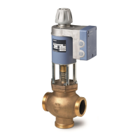
Technical Instructions MXG461 Series Modulating Control Valve
Document Number 125-4461 with Magnetic Actuator
May 3, 2006
Page 8 Siemens Building Technologies, Inc.
Specifications,
Continued
Materials
Valve body Red bronze
Cover flange Red bronze
Seat/Inner valve Stainless Steel
Valve stem seal EPDM (O-ring)
Pipe connections Screwed fittings Bronze/brass
Electrical connections Cable entries 3 × M20 × 1.5 or PG13.5/G1/2
Connection terminals Screw terminals for up to 12 AWG wires
Min. cross-sectional area
1)
0.75 mm
2
Max. cable length See Table 1, 9 (AWG)
Ambient conditions Temperature
Operation
and storage 23°F to 113°F (-5°C to 45°C)
Transport -13°F to 158°F (-25°C to 70°C)
Humidity 5 to 95% rh (non-condensing)
Agency approvals Degree of protection IP31 to IEC 529
Conforms to CE requirements
UL 873
Certified to Canadian standard C22.2 No. 24
C-Tick N-474
PED 97/23/EC:
pressure-carrying parts
Par. 1, section. 2.1.4/Par. 3, section 3
Fluid group 2
Miscellaneous Weight See Figure 18
Dimensions See Figure 18
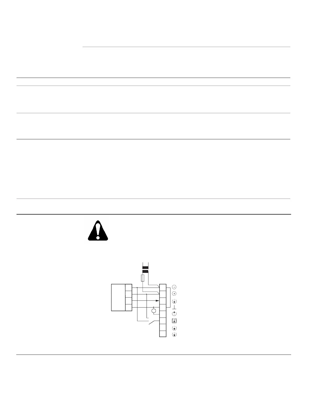
Connection
Terminals
WARNING:
If the controller and the valve receive their power supply from separate
sources, the valve transformer must not be grounded on the secondary
side.
A four-wire connection is mandatory with DC power supply.
Controllers with:
0 to 10 Vdc
2 to 10 Vdc
0 to 20 mA
4 to 20 mA
SSEN0346R1
G0
G
F
Controller
Transformer
AC/DC 24 V Operating voltage
U
U
Z
G0
G
Y
M
0 to 10Vdc / 2 to 10Vdc
0 to 20 mA / 4 to 20 mA
Y
M
0 to 10Vdc / 2 to 10Vdc
0 to 20 mA / 4 to 20 mA
System neutral (SN)
Control signal
System potential (SP)
Measuring neutral (= G0)
Positioning feedback signal
Override input
Figure 14.
1. In case of strong vibrations, use high-flex stranded wires.