Technical Instructions MXG461 Series Modulating Control Valve
Document Number 125-4461 with Magnetic Actuator
May 3, 2006
Page 6 Siemens Building Technologies, Inc.
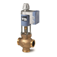
Valve Sizing
Characteristic
SSEN0343R1
10 [V]
10 [V]
20 [mA]
86420
2
4
100
80
60
40
20
0
[%]
90063
6
12
V
Figure 9. Equal Percentage.
SSEN0344R1
10 [V]
10 [V]
20 [mA]
86420
2
4
100
80
60
40
20
0
[%]
90064
6
12
V
Figure 10. Linear.
Installation Notes
•
•
•
•
Installation instructions for the valve and terminal housing are enclosed with the
valve.
Valves are supplied complete with brass/bronze fittings.
The screwed valves are flat-faced to facilitate sealing with the gaskets supplied.
The use of sealing compounds, tape or hemp thread is not recommended.
For electrical installation, see Wiring Diagrams.
CAUTION
:
•
•
•
Always disconnect the power before fitting or removing the terminal
housing. The terminal housing is calibrated and matched to the
actuator, and should be replaced only by qualified personnel.
Use the valve only as a mixing or straight-through valve, not as a
diverting valve. Note the flow direction.
Do not allow the surface temperature of the actuator to fall below the
dew point temperature of the surrounding air (causing condensation).
If necessary, insulate the valve. Do not insulate the actuator.
Use in Straight-through
Applications
Only three-way valves are supplied. These may
be used as straight-through valves by closing off
port B with the accessories supplied (nut, cover
and gasket).
SVAL0230R1
A AB
B
Figure 11. Straight-through
Application.
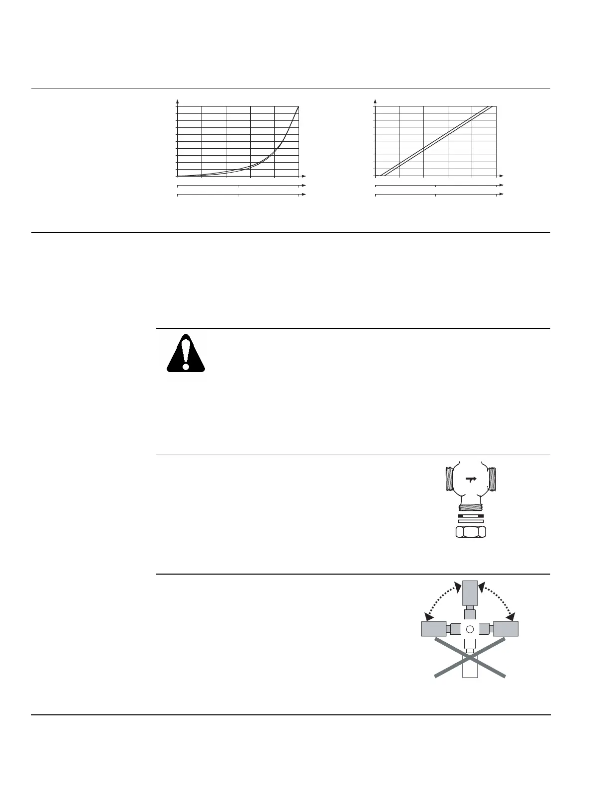
Mounting Position
Vertical to horizontal mounting:
Do not mount the valve below the horizontal.
SSEN0345R1
90 90
IP31IP31
Figure 12. Acceptable Mounting
Positions.