Document No. 565-957
Installation Instructions
August 12, 2005
1. Follow all shutdown procedures necessary to
prevent damage to any equipment or harm to any
personnel.
2. Turn OFF power to the MEC/MBC/RBC en closure.
3. In the MXL enclosure, locate the NIM-1R or
NIM-1W module (hereafter referred to as the
NIM-1 module). This module will be plugged into
the connectors on a MOM-2 or MOM-4 module. If
it is plugged into a MOM-4 module, note w hether
the NIM-1 module is plu gged into the slot closest
to the terminal block labeled TB3 or TB4.
4. If the NIM-1 is plugged into a MOM-2 module,
or if it is plu gged into the slot closest to te rminal
block TB4, the follo win g instruc tions apply to
connections on TB4. If the N IM-1 module is
plugged into a MOM-4 module, in the slot closest
to TB 3, the instructions apply to connec tions on
TB3.
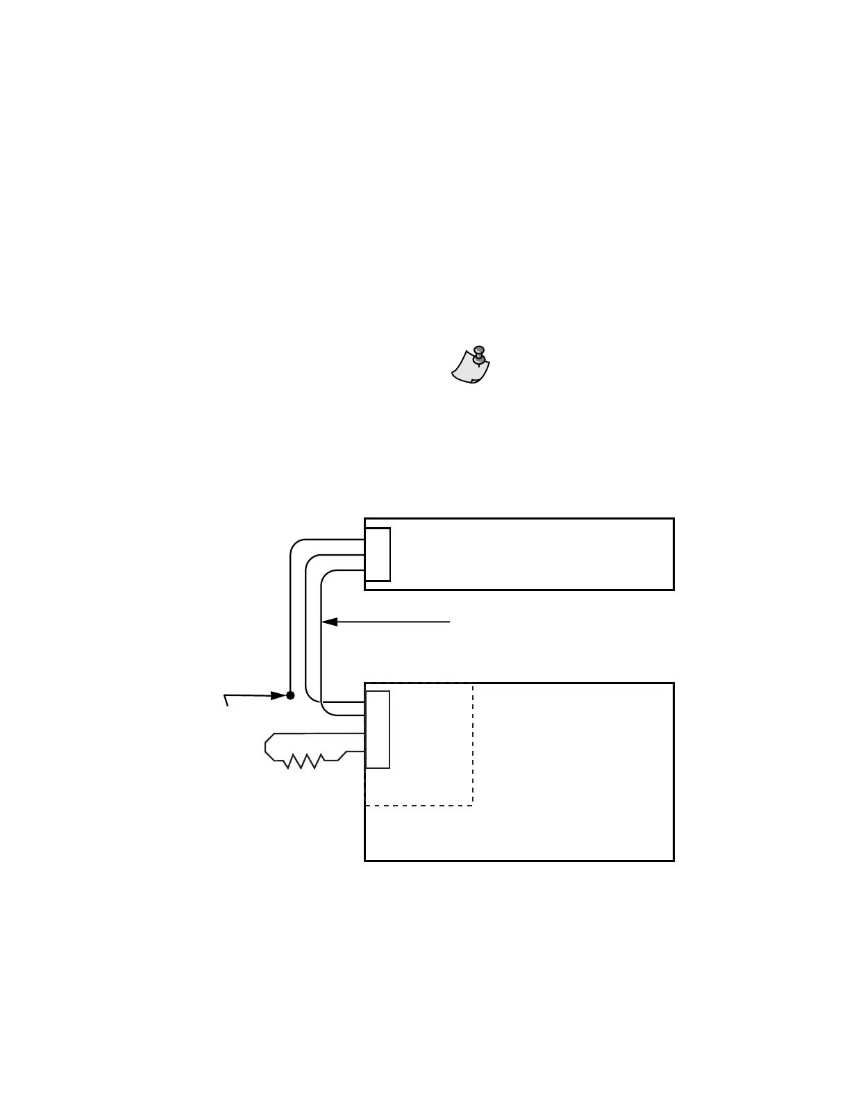
5. Connect one end of the shielded twisted pair
cable to terminal 1 and 2 on the appropriate
terminal block, as specified above. Terminal 1
is the negative (-) terminal, and terminal 2 is
the positive (+) terminal. There is no terminal
available for the shield, so it will be connected at
the driver. (See Figure 1 and Figure 2.)
6. Connect a 120-ohm, 1/4 watt resistor between
terminals 3 and 4 of this same terminal block.
See Figure 2 .
7. At the MEC /MBC/RBC, attach the +, -, and S
leads of the RS-485 cable to an FLN/PMD trunk
connector. Allow an additional 12 inches (305
mm) of cable before terminating to the connector.
The standard practice used by MXL
installers would also require a 120-ohm
resistor between terminals 1 and 2.
Do NOT install a resistor across these
terminals.
8. Turn ON power to the MEC/MBC/RBC enclosure.
9. Start any other equipment that might have been
shut d own fo r this installation.
FLN
DRIVER
S
-
+
MXL PANEL
TAPE BACK
SHIELD
GW1326R1
RS-485 TRUNK CABLE
(MAX 4000’/1219.2 m;
STANDARD 24 AWG LOW CAPACITANCE)
1
2
3
4
TB3
or
TB4
NIM-1 MODULE
120 ohms
1/4 watt
resistor
Figure 1. Connecting the Siemens MXL Driver to the MXL System.
Page 2 of 4
Siemens Building Technologies, Inc.