Do you have a question about the Siemens NCU 7x0.3 PN Series and is the answer not in the manual?
| Product type | Control Unit |
|---|---|
| Communication | PROFINET |
| Operating System | SINUMERIK Operate |
| Power Supply | 24 V DC |
| Protection Class | IP20 |
| Series | NCU 7x0.3 PN |
| Interface | Ethernet |
| Weight | 1.5 kg |
Notices intended for personal safety and preventing damage to products and devices.
Guidelines for handling electrostatically sensitive devices and components.
Describes the modularity, openness, and flexibility of the SINUMERIK 840D sl system.
Details the components and topology of the SINUMERIK 840D sl complete system.
Explains the scalability and different versions of the SINUMERIK 840D sl control units.
Provides order numbers for system components and spare parts.
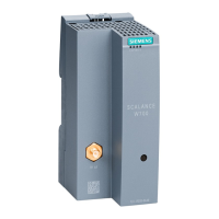
Lists the key elements and interfaces of a Control Unit.
Shows a diagram illustrating the NCU 730.3 PN with its interfaces and elements.
Explains the information found on the side-mounted and front panel type plates.
Details the various controls and indicators on the front of the Control Unit.
Covers grounding concepts and RI suppression measures for system components.
Specifies ambient conditions for shipping, storage, and operation.
Provides guidance on the proper disposal and recycling of the product.
Key safety precautions for installing the Control Unit and related components.
Describes preferred mounting orientations and options for the Control Unit.
Step-by-step instructions for mounting the Control Unit using spacers.
Procedure for directly mounting the Control Unit without using spacers.
Instructions for mounting the NCU 730.3 PN for external cooling via cooling ribs.
Introduces connection options and system topology for the Control Unit.
Essential safety precautions and notices to be observed before and during wiring.
Procedure for safely opening the Control Unit's front cover to access interfaces.
Details the application, pin assignment, and requirements for the external 24 V DC power supply.
Explains the application and pin assignment of DRIVE-CLiQ components.
Describes the application, properties, and pin assignment of Ethernet interfaces.
Covers PROFINET application, properties, pin assignment, and cable specifications.
Details PROFIBUS DP application, properties, pin assignment, and cable specifications.
Explains DIO application, pin assignment, block diagram, and connection procedures.
Describes the NX module, its interfaces, illustration, and mounting.
Details the PP 72/48D PN I/O module's description, technical data, and connections.
Covers the PP 72/48D 2/2A PN I/O module's description, technical data, and connections.
Explains the COM01.3 RS 232C (V.24) option board's description, installation, and connection.
Details the CBE30-2 Ethernet communication board's description, illustration, and installation.
Describes the TM15 Terminal Module and its DRIVE-CLiQ connection.
Explains the TM120 Terminal Module for temperature sensing and its DRIVE-CLiQ connection.
Details the DMC20 Hub Module for DRIVE-CLiQ line distribution.
Describes the DME20 Hub Module for DRIVE-CLiQ line distribution.
Explains the functions and replacement procedure for the dual fan/battery module.
Details the properties and insertion procedure for the mandatory CompactFlash Card.
Provides a list of abbreviations used throughout the manual.
Presents a summary of available SINUMERIK 840D sl documentation.