4BMounting / Installation
| 64
2015-05-04
5.9 Cable entry
The detector bases DB72x have four terminals.
● A maximum of 2 cables may be connected to each screw terminal.
● Only one cable may be connected to each spring clip.
The cable cross section of the terminals is 0.2…1.6 mm
2
.
1a +Connection for external alarm indicator
1b +C-NET IN and OUT
5 -C-NET IN or OUT / -external alarm indicator
6 -C-NET IN or OUT / -external alarm indicator
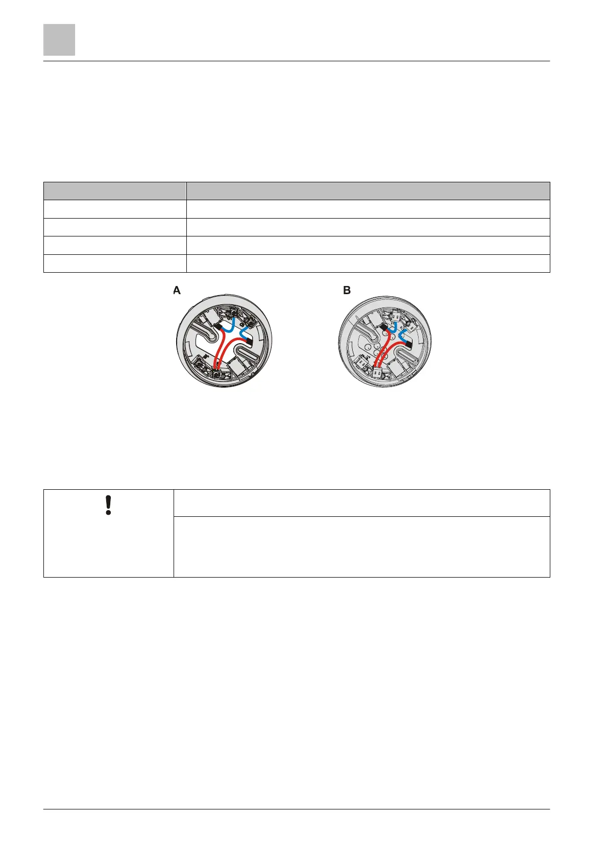
Figure 10: Detector base with screw terminals (A) and spring clips (B)
A
Screw terminals in the detector base DB721/DB720
B
Spring clips in the detector base DB722
Incorrect laying of cables
Damage to cables and difficulties when installing the point detector
● The cable loops must be placed flat in the base bottom.
● The bare length of the cables is approximately 8…10 mm.