EasyManua.ls Logo

Siemens POS8.4420/109 - Mechanical Design; Diagrams

Siemens POS8.4420/109
32 pages
To Next Page IconTo Next Page
To Previous Page IconTo Previous Page
Loading...
Product overview
Mechanical design
2
7 | 32
Siemens
A6V11471220_en--_a
Smart Infrastructure
2018-11-30
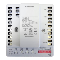
2.4 Mechanical design
1
Gasket for panel mounting
4
KNX PL-Link bus connector
2
Base plate with
screw holes for all common conduit
boxes
guide channels for wiring from center,
up, or bottom
5
Jack connector for tool connection
3
Room operator unit
2.5 Diagrams
2.5.1 Connection terminals
KNX PL-Link plug
Connector
Pin
Description
+
KNX PL-Link (positive)
-
KNX PL-Link (negative)
To find the location of the KNX PL-Link plug, refer to Mechanical design
NOTICE! Users can choose either pair of the pins to connect.

Other manuals for Siemens POS8.4420/109

Related product manuals