Interconnection of PLPA Unit and HF-Connecting Board
Overall Connection Diagram
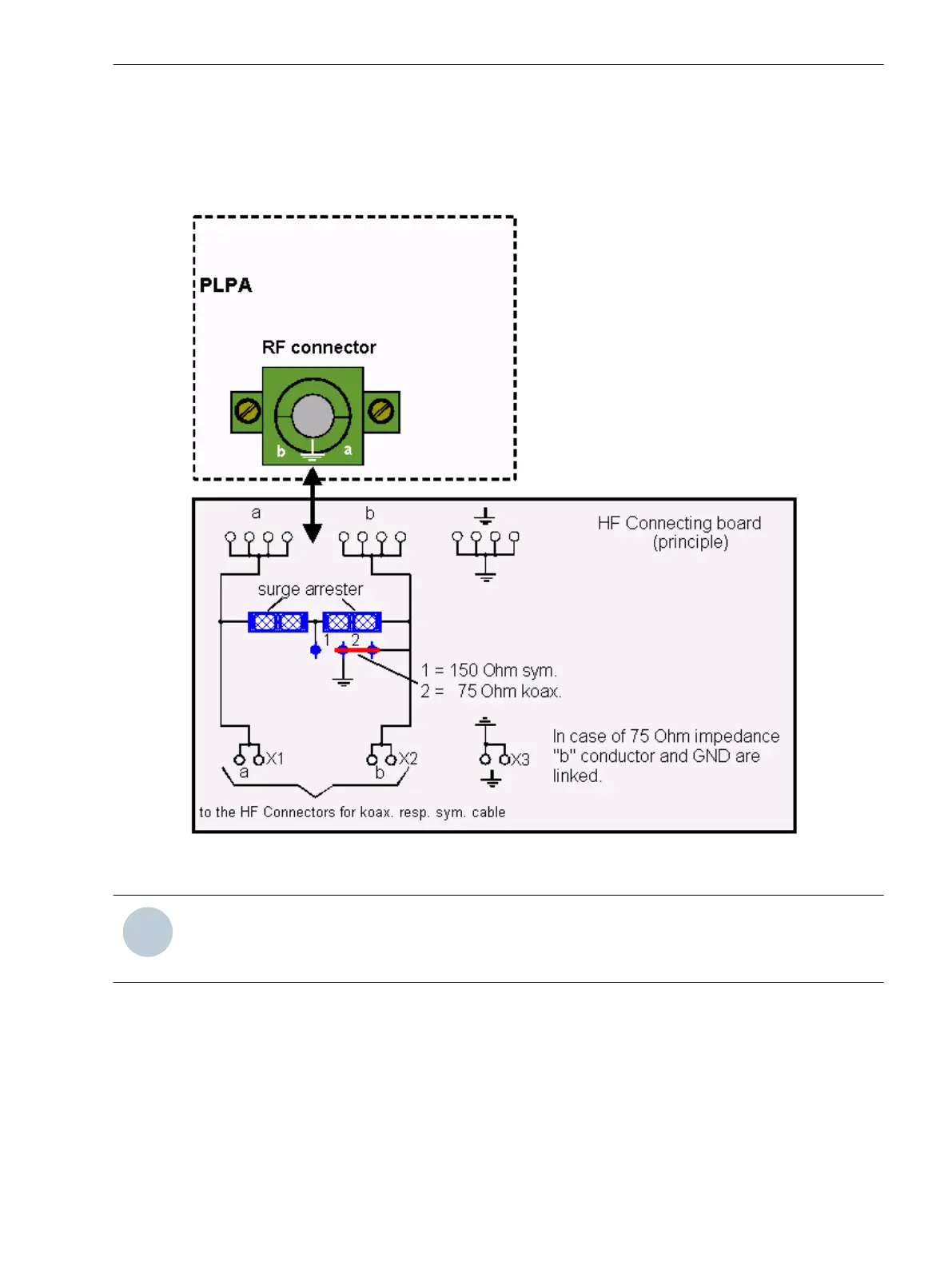
The figure below shows the connection diagram from the PLPA RF connector to the HF connecting board:
[cdplhfcb-241110-01.tif, 1, en_US]
Figure 5-2
Overall connection diagram from the PLE unit to the HF connecting board
NOTE
Please make sure that the “a” and “b” conductors are not exchanged!
In case of 75 Ohm impedance, the “b” wire and GND are linked.
5.2
The Connector Panel
5.2 Interconnection of PLPA Unit and HF-Connecting Board
Smart Communications, PowerLink 100 and PowerLink 50, Product Information 39
E50405-U53-X-B3-7670, Edition 11.2014
 Loading...


