Switching on the Device
After switching on the device (switch S1 enable/disable Power Supply on CSPi, located behind the front
cover, in upper position) the OK LED (green) must light up on the power supply unit and on the CSPi module.
The RX-AL LED must light up green if the device is connected to the transmission line, receiving properly
from the remote station and receive levels are set correctly. Correction of the receive Level is only possible
with the PowerSys service program!
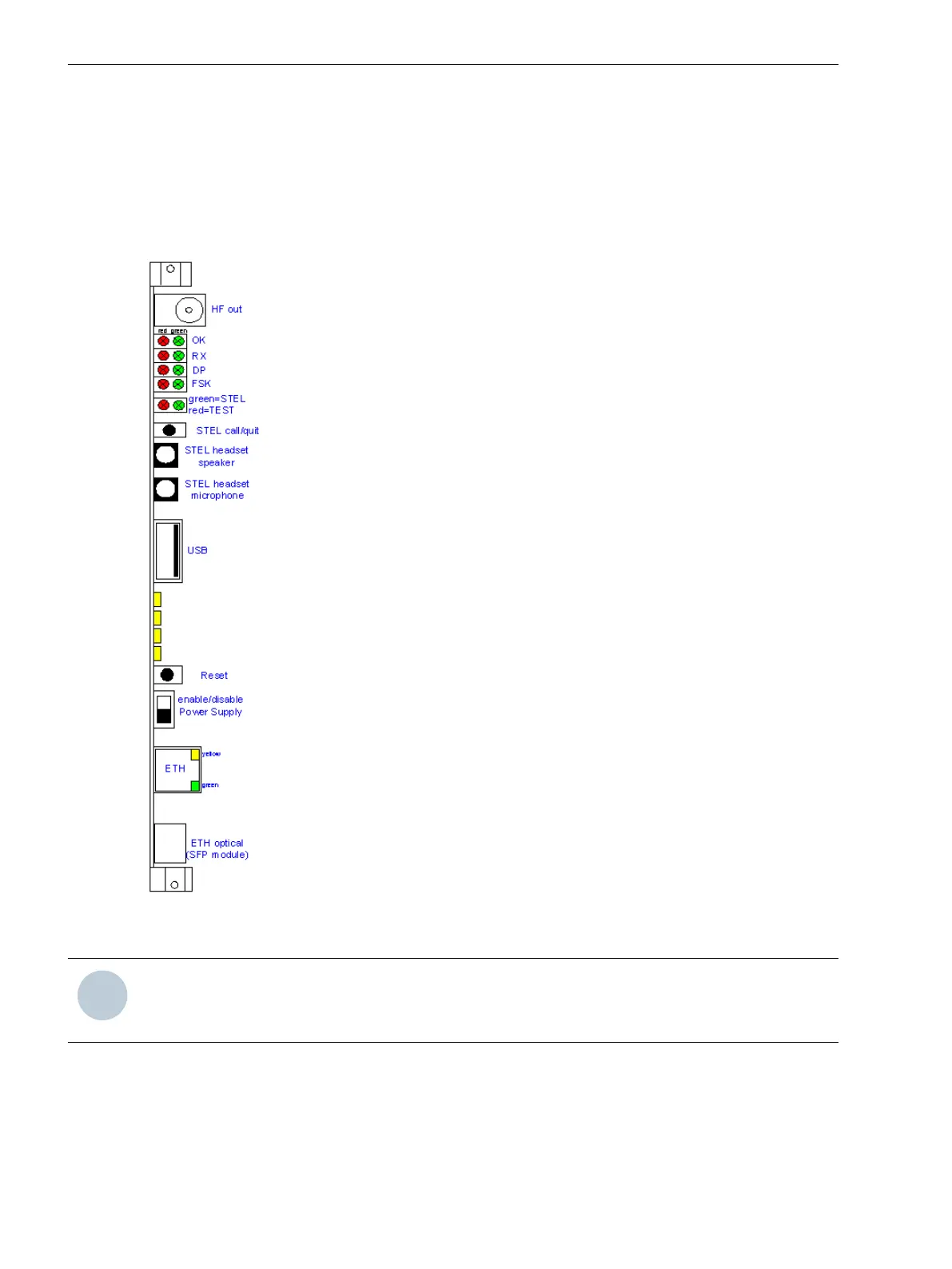
[tdfcppmc-130111-01.tif, 1, en_US]
Figure 6-1
Front cover of the PowerLink processor module CSPi (partial covered)
NOTE
For more details concerning the commissioning of the PowerLink and integrated SWT 3000, we refer you
to the PowerLink Equipment Manual.
6.3
Commissioning
6.3 Switching on the Device
44 Smart Communications, PowerLink 100 and PowerLink 50, Product Information
E50405-U53-X-B3-7670, Edition 11.2014
 Loading...


