Module Slot Positions in the PowerLink 50
[dw_powerlink50s-231014, 1, --_--]
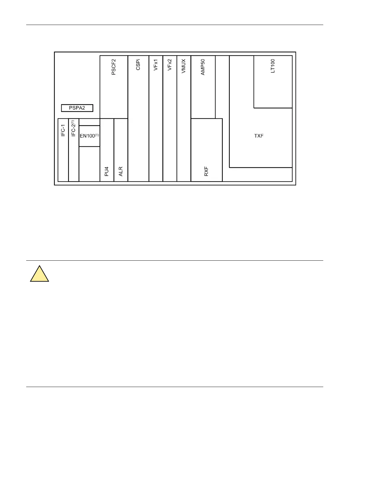
Figure 6-3 Slot positions of the PowerLink 50 Modules
(1) IFC-2 or EN100
Exchanging/Mounting Modules
This instruction applies for exchanging resp. mounting modules in the CFS part. The module position in the
CFS part is shown in the figure Slot positions of the PowerLink modules
It is not allowed to insert or remove modules in the PowerLink when the power supply is enabled!
CAUTION
Electrostatic sensitive devices are protected against destruction by electrostatic charge with protective
structures at the inputs and outputs. In unfavorable cases, however, plastic floor coverings, non-conduc-
tive work surfaces, or clothing containing artificial fibers can result in such high charges.
These charges can damage or even destroy the electrostatic sensitive devices despite the protective
networks mentioned. If a device is damaged, its reliability decreases drastically although the effects of the
damage are noticeable a long time before.
²
In order to ensure that electrostatic charges are completely eliminated when working on the system,
comply with the following instructions in order to avoid moderate or minor damage:
²
- Before carrying out any work on the system, ground yourself with a wrist strap.
²
- When working on modules, always place them on a grounded conductive surface.
²
- Transport modules only in suitable protective bags.
For mounting (exchanging) modules in the PowerLink 50/100 system please observe the following instruction:
•
Remove the cover of the CFS-2 module section (4 screws).
•
Disable the power supply (move the switch S1 on the CSPi module above PC connector into lower posi-
tion).
In case of exchanging a module:
•
Remove the existing module and place it on a grounded, conductive surface.
Commissioning
6.4 Mounting of Modules in the PowerLink
46 Smart Communications, PowerLink 100 and PowerLink 50, Product Information
E50405-U53-X-B3-7670, Edition 11.2014
 Loading...


