Compact Series Product Overview
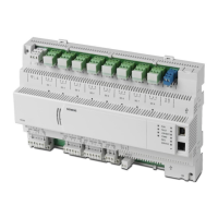
16- and 24-Point Compact Series Diagram
Technical Reference Manual
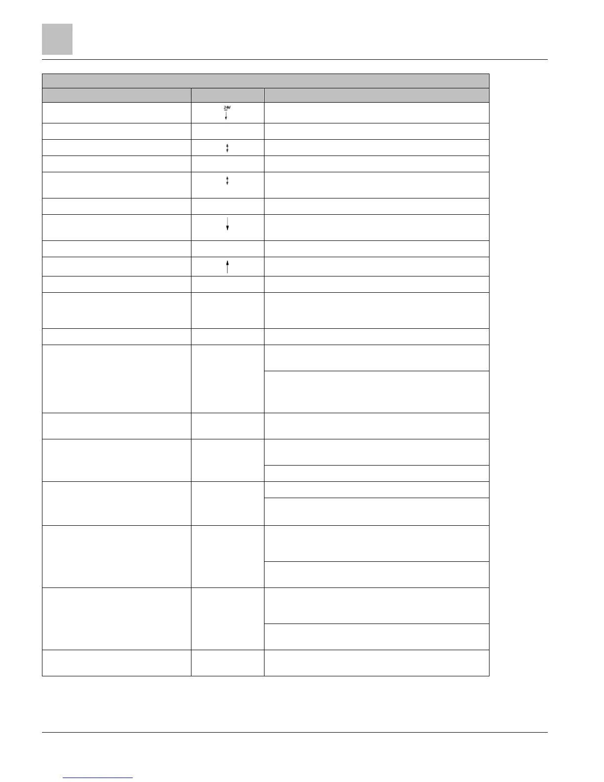
PXC-16 and PXC-24 Features, Symbols, and Status LEDs.
Terminal Block Connection
24 Vdc external sensor power (+) source.
38, 40
–
Signal Common.
41, 43, 44, 46
Universal Input/Output (+) PXC-24 only (U9 through U12).
42, 45
–
Signal Common (PXC-24 only).
47, 49, 50, 52
Super Universal Input/Output (+) PXC-24 only (X13 through
X16).
48, 51
–
Signal Common.
53, 55, 57
Analog Output (+) (PXC-16: AO9 through AO11; PXC-24:
AO17 through AO19).
54, 56
-
Signal Common.
58, 60
Digital Input (+) PXC-16 only (DI12 through DI13).
59
–
Signal Common (PXC-16 only).
D
HMI
Human-Machine Interface port
(RS-232 8-N-1 signal, RJ-45 8 pin connector, service only, will
not dial out.)
(green)
ON - Normal steady Green, unit is powered and running. May
briefly flash while processor is booting.
OFF - Error.
● 24 Vac input is not present.
● Power is ON, but the application firmware has not booted.
FAULT LED
(red)
(for future use)
Normal Off, not currently implemented. May be Red if
processor does not complete boot.
LOW BATT LED
Error. RAM Battery (AA) is dead, low, missing or shipping
tab is not removed.
OFF - Normal operation.
Ethernet COMM LED
(yellow)
(BACnet/IP or
Ethernet TCP/IP
(P2) only)
ON - Linked to Ethernet hub.
OFF - No link to Ethernet hub.
RS-485 TX
(yellow) (RS-485
only)
Flashing - Transmitting information over the RS-485, RS-485
P2 or BACnet MS/TP ALN or P1 or MS/TP FLN (depending on
how the port is defined).
OFF or ON solid - No device, no connection, or bad
connection.
RS-485 RX
(yellow) (RS-485
only)
Flashing - Receiving information over the RS-485, RS-485 P2
or BACnet MS/TP ALN or P1 or MS/TP FLN (depending on
how the port is defined).
OFF or ON solid - No device, no connection, or bad
connection.
PXC-16: DO 14 through DO 16; PXC-24:
DO 20 through DO 24
 Loading...