38 / 94
Siemens RDF301, RDF301.50..., RDF600KN, RDF600KN/S Basic Documentation CE1P3171en
Building Technologies 2017-12-07
3.6.3 2-pipe fan coil unit
On 2-pipe applications, the thermostat controls a valve in heating / cooling mode
with changeover (automatically or manually), heating only, or cooling only. Cooling
only is factory-set (P01 = 1).
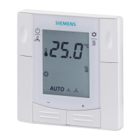
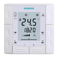
ON/OFF control
The diagrams below show the control sequence for 2-position control.
Heating mode Cooling mode
½ SDH
T[°C]
Y1
T[°C] Room temperature SDH Switching differential "Heating" (P30)
w Room temperature setpoint SDC Switching differential "Cooling" (P31)
Y1 Control command "Valve" or "Compressor"
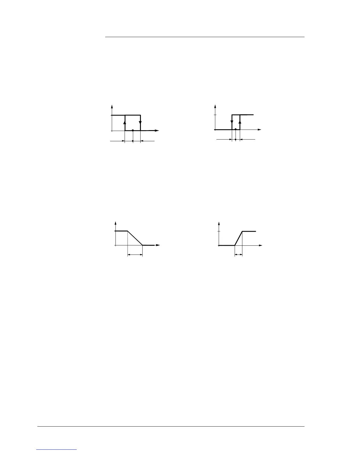
Modulating control: 3-position
The diagrams below show the control sequence for modulating PI control.
Heating mode Cooling mode
XpH
100
0
w
T[°C]
Y1
T[°C] Room temperature XpH Proportional band "Heating" (P30)
w Room temperature setpoint XpC Proportional band "Cooling" (P31)
Y1 Control command "Valve"
∂ The diagrams only show the PI thermostat’s proportional part.
∂ For the fan sequence see section 3.8.
Setting the sequence and the control outputs
Refer to section 3.4, section 3.6.1 and section 3.7.
Control sequence
ON/OFF output
Control sequence
modulating output
Notes:
 Loading...