28 / 60
Siemens RDG100…/RDG110…/RDG140.../RDG160… Basic Documentation CE1P3076.en
Building Technologies Functions 28 May 2009
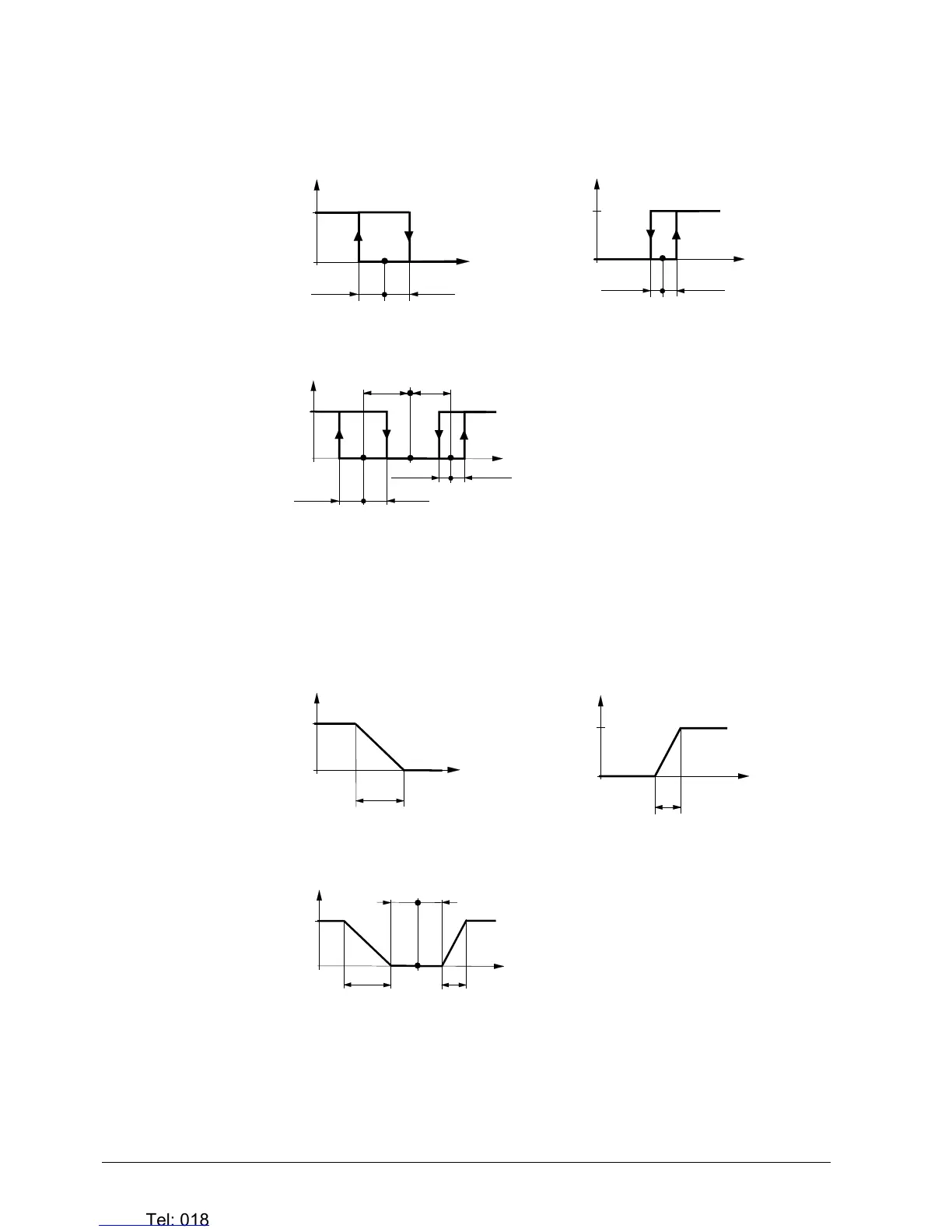
The diagram below shows the control sequence for 2-position control.
Heating mode with manual selection
(P01=2)
Cooling mode with manual selection
(P01=2)
½ SDH
1
0
½ SDH
w
Y
3076D01
T[°C]
Y1
Y
½ SDC
1
0
½ SDC
w
3076D13
T[°C]
Y2
Heating and cooling mode (P01=04)
T[°C] Room temperature
w Room temperature setpoint
Y1 Control command “Valve” or “Comp.” (H)
Y2 Control command “Valve” or “Comp.” (C)
SDH Switching differential “Heating” (P30)
SDC Switching differential “Cooling” (P31)
Y
½ SDC
1
0
½ SDC
w
3076D11
T[°C]
Y2
½ SDH
½ SDH
Y1
½
x
dz
½
x
dz
X
dz
Dead zone (P33)
Modulating control: 3-position, PWM or DC 0…10 V
The diagram below shows the control sequence of modulating PI control.
Heating mode with manual selection
(P01=2)
Cooling mode with manual selection
(P01=2)
XpH
100
0
w
Y [%]
3076D03
T[°C]
Y1
XpC
Y [%]
100
0
w
3076D14
T[°C]
Y2
Heating and cooling mode (P01=04)
T[°C] Room temperature
w Room temperature setpoint
Y1 Control command “Valve” heating
Y2 Control command “Valve” cooling
XpH Proportional band “Heating” (P30)
XpC Proportional band “Cooling” (P31)
Y [%]
100
0
w
3076D12
T[°C]
Y2
XpH
Y1
XpC
½ x
dz
½
x
dz
X
dz
Dead zone (P33)
The diagrams only show the PI controller’s proportional part.
Setting the sequence and the control outputs
Refer to sections 4.5 (applications), 4.7.1 (sequences) and 4.7.2 (outputs).
ON/OFF cont
rol
Note

 Loading...