54 / 60
Siemens RDG100…/RDG110…/RDG140.../RDG160… Basic Documentation CE1P3076.en
Building Technologies Engineering 28 May 2009
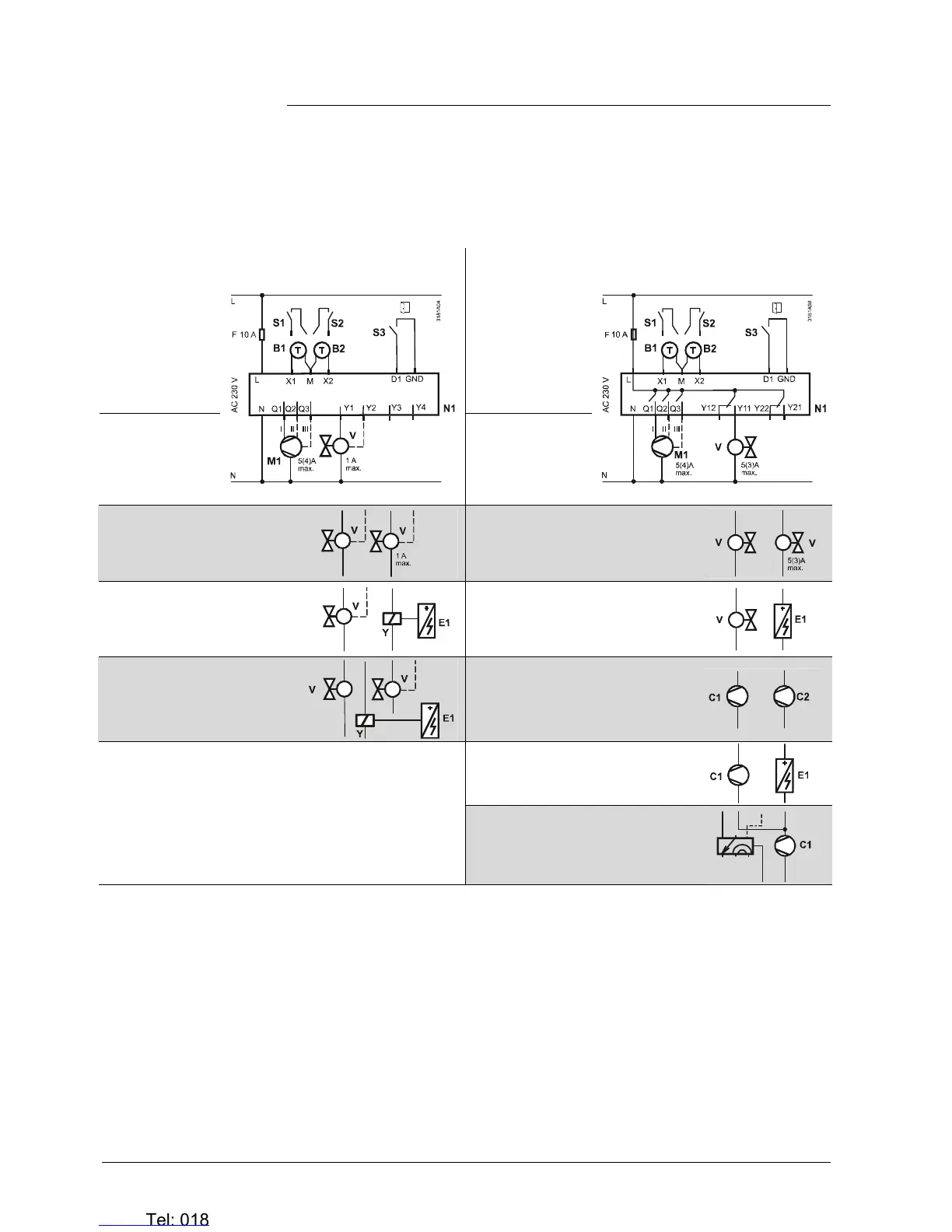
6.2 Connection diagrams
For details concerning connection of peripheral devices and setting of the DIP
switches, please refer to the Mounting Instructions:
– M3181.1 (RDG100, RDG100T)
– M3181.2 (RDG110)
– M3181.3 (RDG140, RDG160)
RDG100…
RDG110
1- or 3-speed fan
1- or 3-speed fan
• 2-pipe
• 2-pipe
• 2-pipe & radiator
• 4-pipe
• 2-stage
• 2-pipe & radiator
• 4-pipe
• 2-stage
• 2-pipe & el. heater
• 2-pipe & el. heater
• 4-pipe & el. heater
• 1 and 2-stage compressor
• Compressor & el. heater
• Compressor & reversing valve
RV
N1 Room thermostat RDG1…
M1 1- or 3-speed fan
V Valve actuators:
ON/OFF or PWM, 3-position, heating, cooling,
radiator, heating / cooling, 1st or 2nd stage
E1 Electrical heater
C1, C2 Compressor
S1, S2 Switch (keycard, window contact, etc.)
S3 Switch at SELV input (keycard, window contact)
B1, B2 Temperature sensor (return air temperature,
external room temperature, changeover sensor,
floor temperature limit, etc.)
RV Reversing valve
Q Relay outputs
Y1...Y4 Triac outputs
Y11…Y22 Relay outputs
Note

 Loading...