36 / 60
Siemens RDG100…/RDG110…/RDG140.../RDG160… Basic Documentation CE1P3076.en
Building Technologies Functions 28 May 2009
2. When the thermostat calculates the positions "fully close" or "fully open", the
actuator running time is extended by 150% to ensure the right actuator position
is synchronized to the control algorithm.
3. After the actuator reaches the position calculated by the thermostat, a waiting
time of 30 seconds is applied to stabilize the outputs.
This function is available with RDG100 and RDG100T only.
The demand calculated by PI control from the current room temperature and set-
point is provided via Y1 and Y3 to the valve actuator as a PWM signal (pulse width
modulation) for thermal actuators. The output is activated for a period proportional
to the heating / cooling demand and then switched off for the rest of the PWM
interval.
The interval is 150 seconds (factory setting). It can be adjusted via parameters
P44 (Y1) or P45 (Y3). These parameters are only visible if 2-position is selected via
DIP switches 4 and 5 and if PWM is selected via P46 and P47.
For thermal valve actuators, set the running time to 240 seconds.
• Never apply PWM to an electromotoric actuator
• It is not possible to ensure exact parallel running of more than one thermal valve
actuator. If several fan coil units are driven by the same thermostat, preference
should be given to electromotoric actuators
For electrical heaters, set the running time to 90 seconds.
To avoid burn-off of mechanical contacts by frequent switching, use a current valve
in place of a relay or contactor.
This function is available with RDG140 and RDG160 only.
The demand calculated by PI control from the current room temperature and
setpoint is provided via Y10 and Y20 to the valve actuator as a continuous
DC 0...10 V signal.
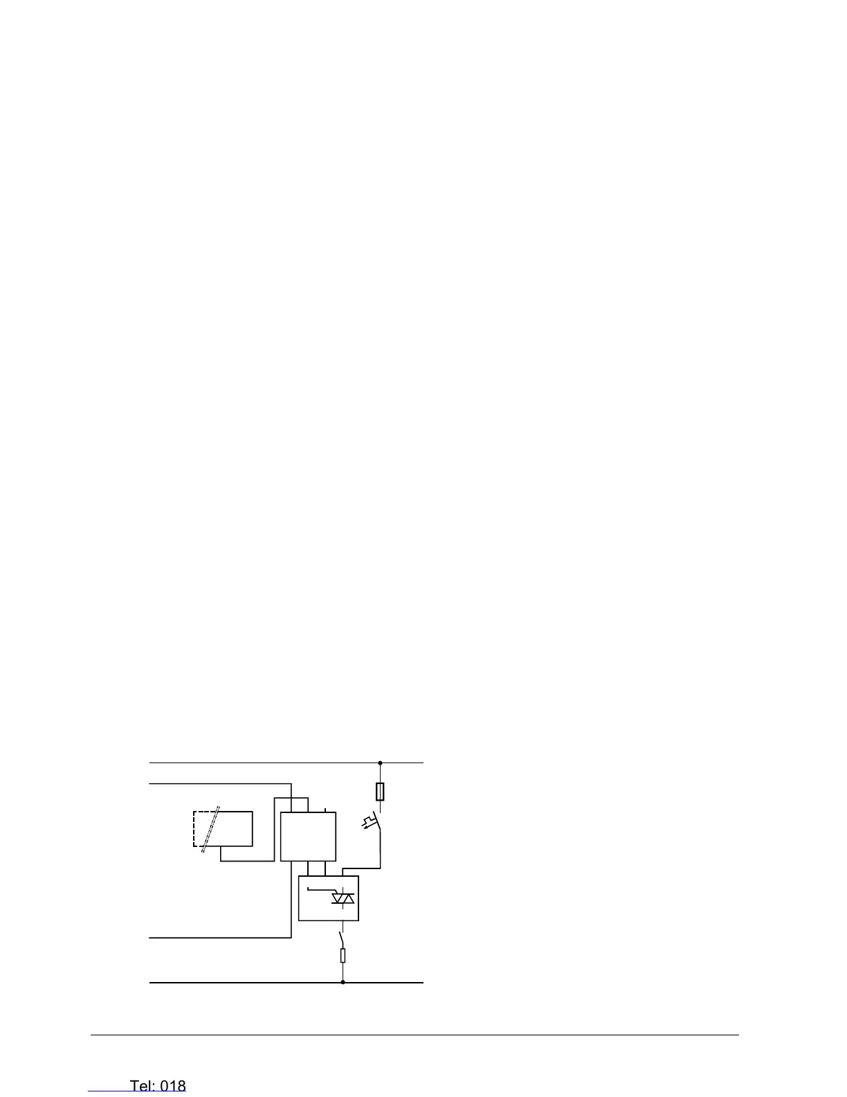
• The demand calculated by PI control from the current room temperature and
setpoint is provided via Y20 as a continuous DC 0...10 V signal.
• The signal converter (SEM61.4) converts the DC 0...10 V signal to AC 24 V
PDM pulses for the current valve
• The current valve (SEA45.1) supplies the electrical heater with AC 50…660 V
pulsed current
YE
DC 0 ... 10 V
Y1 G
L
N
Y1 L
Q
5.7 kW
max.
N1
U1
FF
F...
Y1
K...
G0
G
G
3181D21
G
G0
Y
PWM
AC 24 V
N1 RDG140, RDG160
U1 Signal converter SEM61.4 (see Data Sheet N5102)
Y1 Current valve SEA45.1 (see Data Sheet N4937)
K… Safety loop (e.g. safety thermostat and high-
temperature cutout)
FF Very fast-acting fuse
F… Overcurrent trip
PWM control
PWM for thermal
valve actuators
Note!
PWM for electrical
heaters
DC 0...10 V control
DC 0...10 V
for valve actuators
DC 0...10 V
for electrical heaters

 Loading...