30 / 66
Siemens RDG100, RDG100T, RDG110, RDG140, RDG160 Basic Documentation CE1P3181en
Building Technologies Functions 14 Dec 2011
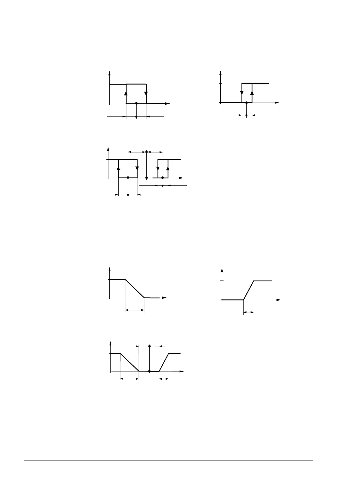
The diagrams below show the control sequence for 2-position control.
Heating mode with manual selection
(P01=2) or
for P09 >= P10 in heating sequence *)
Cooling mode with manual selection
(P01=2) or
for P09 >= P10 in cooling sequence *)
½ SDH
1
0
½ SDH
w
Y
3191D01_01
T[°C]
YH
Y
½ SDC
1
0
½ SDC
w
3191D13
01
T[°C]
YC
Heating and cooling mode (P01=04)
T[°C] Room temperature
w Room temperature setpoint
YH Control command “Valve” (heating)
YC Control command “Valve” (cooling)
SDH Switching differential “Heating” (P30)
SDC Switching differential “Cooling” (P31)
Y
½ SDC
1
0
½ SDC
w
3191D11
T[°C]
YC
½ SDH
½ SDH
YH
½
x
dz
½
x
dz
X
dz
Dead zone (P33)
Modulating control: 3-position or PWM
The diagrams below show the control sequence of modulating PI control.
Heating mode with manual selection
(P01=2) or
for P09 >= P10 in heating sequence *)
Cooling mode with manual selection
(P01=2) or
for P09 >= P10 in cooling sequence *)
XpH
100
0
w
Y [%]
3191D03_01
T[°C]
YH
XpC
Y [%]
100
0
w
3191D14
T[°C]
YC
Heating and cooling mode (P01=04)
T[°C] Room temperature
w Room temperature setpoint
YH Control command “Valve” (heating)
YC Control command “Valve” (cooling)
XpH Proportional band “Heating” (P30)
XpC Proportional band “Cooling” (P31)
Y [%]
100
0
w
3191D12
T[°C]
YC
XpH
YH
XpC
½ x
dz
½
x
dz
X
dz
Dead zone (P33)
*) P09, P10 with SW V7.2 and later / device index E, see section 4.3.
The diag
rams only show the PI controller’s proportional part.
Setting the sequence and the control outputs
Refer to sections 4.5 ("Applications"), 4.7.1 ("Sequences") and 4.7.2 ("Outputs").
ON/OFF c
ontrol
Note

 Loading...