RUGGEDCOM RSG907R
Installation Guide
Chapter 2
Installing the Device
Wiring Examples 15
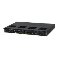
HI Power Supply
a. Connect the Line wire (AC) or Positive wire (DC)
to the positive/live (+/L) terminal on the terminal
block.
b. Connect the Neutral wire (AC) or Negative wire
(DC) to the negative/neutral (-/N) terminal on
the terminal block.
c. Connect the ground wire to the chassis/ground
terminal on the terminal block.
LO Power supply
a. Connect the Positive wire to the positive (+)
terminal on the terminal block.
b. Connect the Negative wire to the negative (-)
terminal on the terminal block.
c. Connect the ground wire to the chassis/ground
terminal on the terminal block.
Figure10:Terminal Block Wiring
1.3 POS Terminal Block 2.5 POS Terminal Block 3.Chassis/
Ground Terminal 4.Negative Terminal 5.Positive Terminal
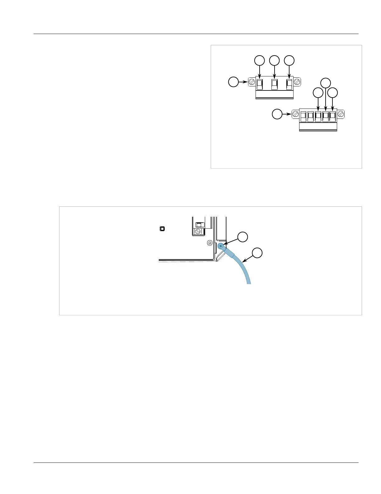
4. Connect the chassis ground screw to ground (Potential Earth). It is recommended to terminate the ground
connection with an M4 ring or spade lug, and then torque to 1.7 N·m (15 lbf-in).
Figure11:Chassis Ground Connection
1.M4 Screw 2.M4 Ring Lug
5. Connect the power cable to the power source.
Section2.6.2
Wiring Examples
The following illustrate how to connect single and dual power supplies to the device.
 Loading...