Siemens Industry, Inc.
Building Technologies Division
P/N 315-050537-323
INTRODUCTION This section briefly describes special programming considerations for the NCC
associated with the Ethernet fiber switches. Please refer to the NCC Manual, P/N
315-049679, for more detailed information.
NCC PROGRAMMING NCCs are located in the Fire Command Centers and are connected to the Fiber Optic
switch at the FCC. There are a maximum of four NCCs in the entire complex for
legacy system, and a maximum of two NCCs for FVNET network system.
• Example of IP address range is 192.168.1.1 – 192.168.1.64
• XNET Address Node ID range is 1-64
• NCC database requires Node IDs from all nodes in all XLS systems
• NCC requires Node IDs and IP address information from:
- NCC
- Fiber Optic Switch
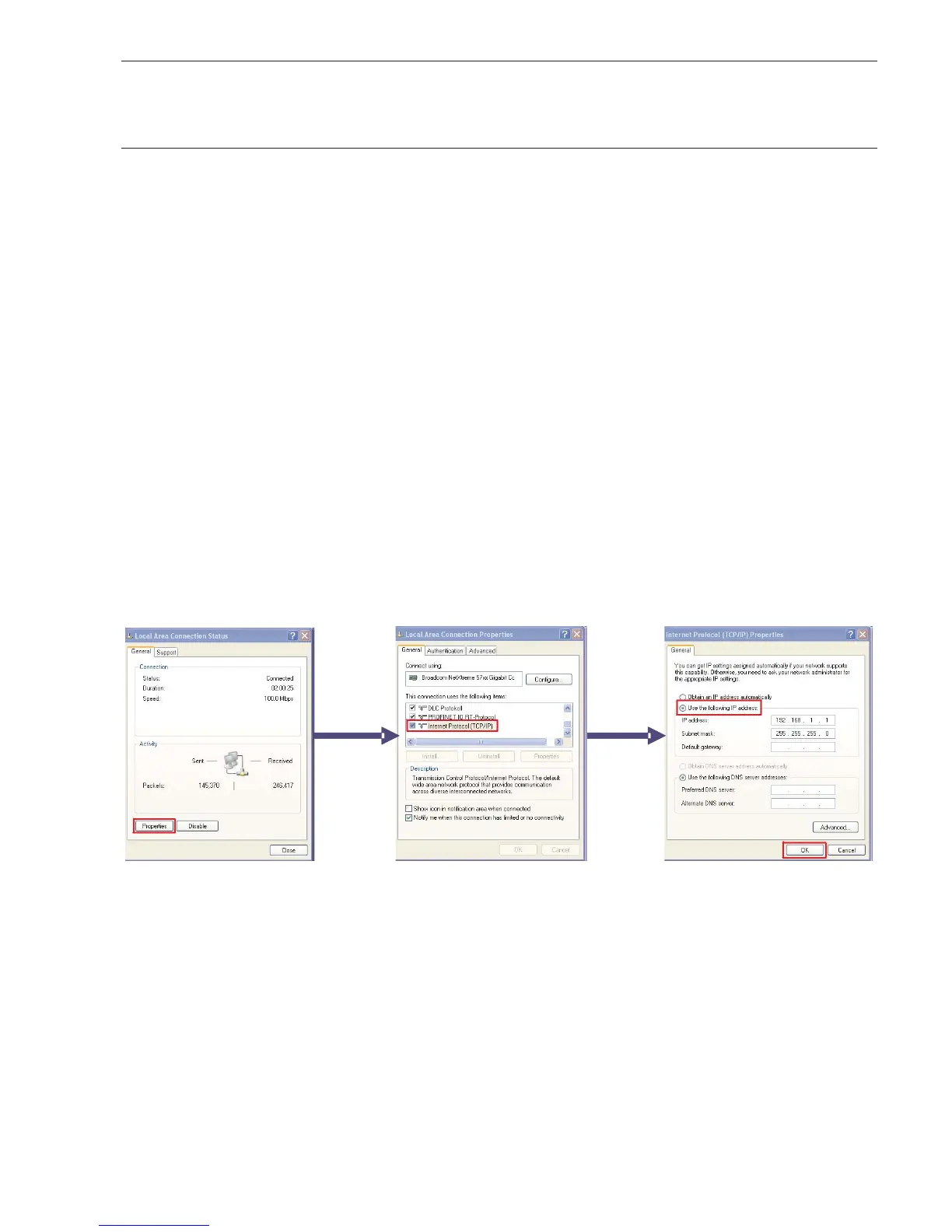
Initial Setup To setup the IP address of the NCC execute the following steps:
• From the desktop click Start->Network Connections->Local Area Connection.
• From the Local Area Connections Status window click Properties.
• From Local Area Connections Properties window click on Internet Protocol
then properties.
• From Internet Protocol Properties window choose Use the following IP
address and choose and IP address in the range 192.168.1.60 - 192.168.1.63
with the subnet mask of 255.255.255.0.
Figure 30
IP Address Setup
 Loading...