10/80
Siemens Building Technologies Commissioning Guide CM1G5192en
HVAC Products 4 EMC-compatible installation of SED2 26.02.2003
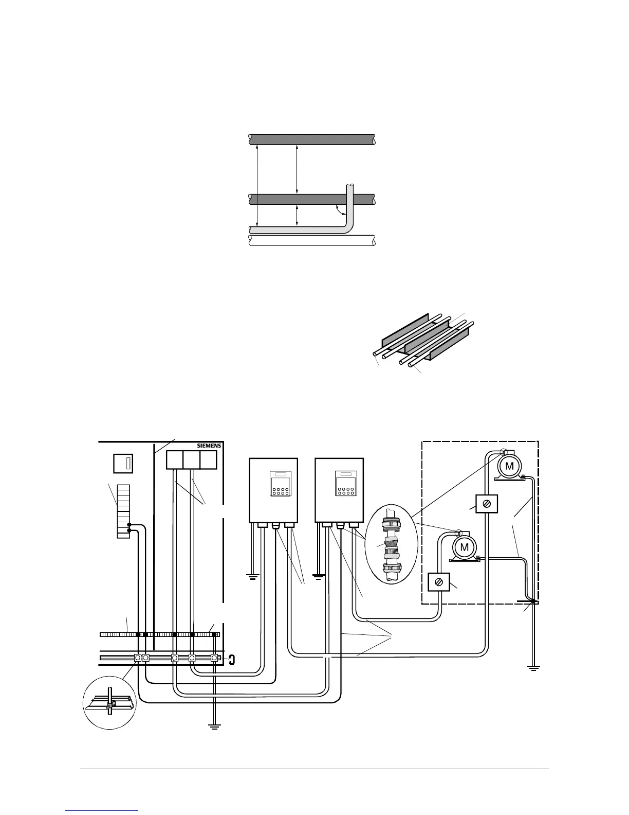
4.4.2 Routing of cables
• Lay cables of different power sections, such as control, mains and motor cables, separately
• Avoid undesired coupling caused by parallel running control, power and motor cables
• Lay control, mains and motor cables separately, in separate cable ducts at a distance of at least 200 mm (see
illustration below). If cables must be crossed, run them at an angle of 90° if possible
90°
> 40 cm > 20 cm
> 20 cm
5192Z37en
Motor cable
Mains cable
Signal cable
Signal / control cable
• Keep cables to motors as short as possible, generally not exceeding 25 m
• If possible, lay external cables in sheet metal ducts or on metal carriers. The metal cable duct or carrier should
be earthed and its individual parts should be galvanically connected
• If it is not possible to run control, power and motor ca-
bles separately in separate cable ducts or cable carri-
ers, the cable duct or carrier must at least have metallic
galvanically conductive partitions
Metal partition
5
1
9
2
Z
4
5
e
n
Motor cable
Signal and
control cables
IP 54: Example of EMC-compatible installation and wiring of the SED2
BMS
F1 F2
III III
SED2 / IP54
SED2 / IP54
*
*
*
*
Connection and
potential
equalization rail
Extract air
Supply air
Extract airSupply air
Metal
cable glands
Strain
relief rail
Min.16 mm
2
Control cabinet
Monoblock
Metal partition
I/O modules
Plastic cable gland
Power Supply
cable unshielded
Connection
terminals
Shielded cables
Potential
equalization
Metal
cable gland
Shielding
Service
switch
Service
switch
5192Z33en
* All potential equalization cables must have
a cross-sectional area of at least 16 mm
2

 Loading...


