31/80
Siemens Building Technologies Commissioning Guide CM1G5192en
HVAC Products 7 Application examples 26.02.2003
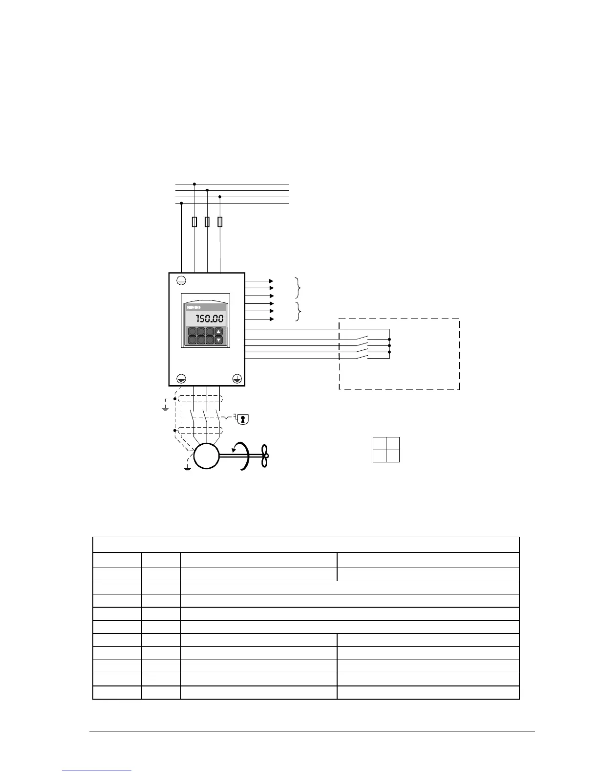
7.2 Application example 2
A motor shall run at 4 fixed speeds.
− Control is accomplished via digital inputs
− Error message via relay output 1
− Indication of operation via relay output 2
Note: With the settings for this application example, the assumption is made that the parameters use their de-
fault values and that the connected motor has been commissioned with the standard parameters.
If several digital inputs are active at the same time, the setpoint will be added up.
The VSD is started when one of the inputs assumes the ON position.
Hand
Auto
SE D2
0
I
P
Fn
P(1)
Hz
L1
L2
L3
PE
L1 L2 L3
20
uvw
M
9
5
6
7
8
21
22
23
24
25
Fuses
Inspection switch
Fan
Building Management System (BMS)
or
speed selector switch
5192A02en
Fixed frequency 1
Fixed frequency 2
Fixed frequency 3
Fixed frequency 4
Error
Com
Run
Com
Relay 1
Relay 2
7.2.1 Parameter changes
Start with quick commissioning according to application example 1
Par. no. Value Parameter function Function selection
P0003 3 User access level Expert access
P0701(0) 16 VSD starts with fixed frequency 1
P0702(0) 16 VSD starts with fixed frequency 2
P0703(0) 16 VSD starts with fixed frequency 3
P0704(0) 16 VSD starts with fixed frequency 4
P1000 3 Selection of frequency setpoint (2 = analog, 3 = digital)
P1001 10 Hz Selection fixed frequency setpoint (Hz)
P1002 20 Hz Selection fixed frequency setpoint (Hz)
P1003 30 Hz Selection fixed frequency setpoint (Hz)
P1004 40 Hz Selection fixed frequency setpoint (Hz)
DIP switch setting
ON 1 = analog input 1
OFF
❚❚
OFF = DC 0…10 V
1 2 ON = 0…20 mA
2 = analog input 2
OFF = DC 0…10 V
ON = 0…20 mA

 Loading...


