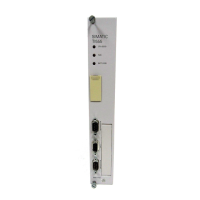
Installlation
2-2
SIMATIC 505–2556 Installation and Operation Guide
2.1 Getting Started
The
installation of the SIMA
TIC 505–2556 Sixteen Channel Thermocouple
Input Module involves the following steps:
1.
Planning the installation
2.
Configuring the module
3.
Inserting the module into the I/O base
4. W
iring the module input connector
5.
Checking module operation
The steps listed above are explained in detail in the following pages.
Planning is the first step in the installation of the module. This involves
calculating the I/O base power budget and routing the input signal wiring to
minimize noise. The following sections discuss these important
considerations.
The SIMA
TIC 505–2556 requires 5 watts of +5 VDC power from the I/O
base. Use these values to verify that the base power supply capacity is not
exceeded.
Open the shipping carton and remove the special anti–static bag which
contains the module.
!
CAUTION
The
components on the SIMA
TIC 505–2556 module printed circuit card can be
damaged by static electricity discharge. T
o prevent this damage, the module is
shipped in a special anti-static bag.
Static control precautions should be followed when removing the module from
the bag, when opening the module, and when handling the printed circuit card
during configuration.
After
discharging any static build–up, remove the module from the static
bag. Do not discard the static bag. You will need it for the following
configuration procedure.
Planning the
Installation
Calculating the I/O
Base Power Budget
Unpacking the
Module

 Loading...


