Displays and interrupts
5
5.1 Status and error displays of the I/O module DI 8x24…125VDC HA
[ID: 80184678667]
LED displays
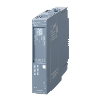
The following figure shows the LED displays of the I/O module.
DIAG MT
DI
HA
8x24 ..12 5 VDC
7
DI . 6 +
8
1
DI . 0 +
2
3
DI . 2+
4
5
DI . 4 +
6
1P1
L+
24 VD C
M
1P2
2P1
L+
24 VD C
M
2P 2
MA X. 10 A
.0 .1
V 1.0 .0
CC 42
PW R
6DL1131-6DF00 -0PK 0
X
2
3 4
DI .7+
DI .1+
DI . 3 +
DI . 5 +
DI
15
16
9
10
11
12
13
14
F0 F1
.2 .3
F2 F3
.4 .5
F4 F5
.6 .7
F6 F7
2M
① DIAG LED (green/red)
② MT LED (yellow)
③ Channel status LED (green)
④ Channel fault LED (red)
⑤ PWR LED (green)
Figure 5-1 LED displays
Meaning of the LED displays
The following tables show the meaning of the status and error displays for the I/O module.
Measures for dealing with diagnostics messages can be found in the section Diagnostics
messages and maintenance events (Page 32).
Digital input module DI 8x24...125VDC HA (6DL1131-6DF00-0PK0)
Manual, 11/2017, A5E39288633-AB 17

 Loading...


