Communication using function blocks
6.3 Using the function blocks for connecting to a communications processor
PtP coupling and configuration of CP 340
108 Manual, 04/2011, A5E00369892-03
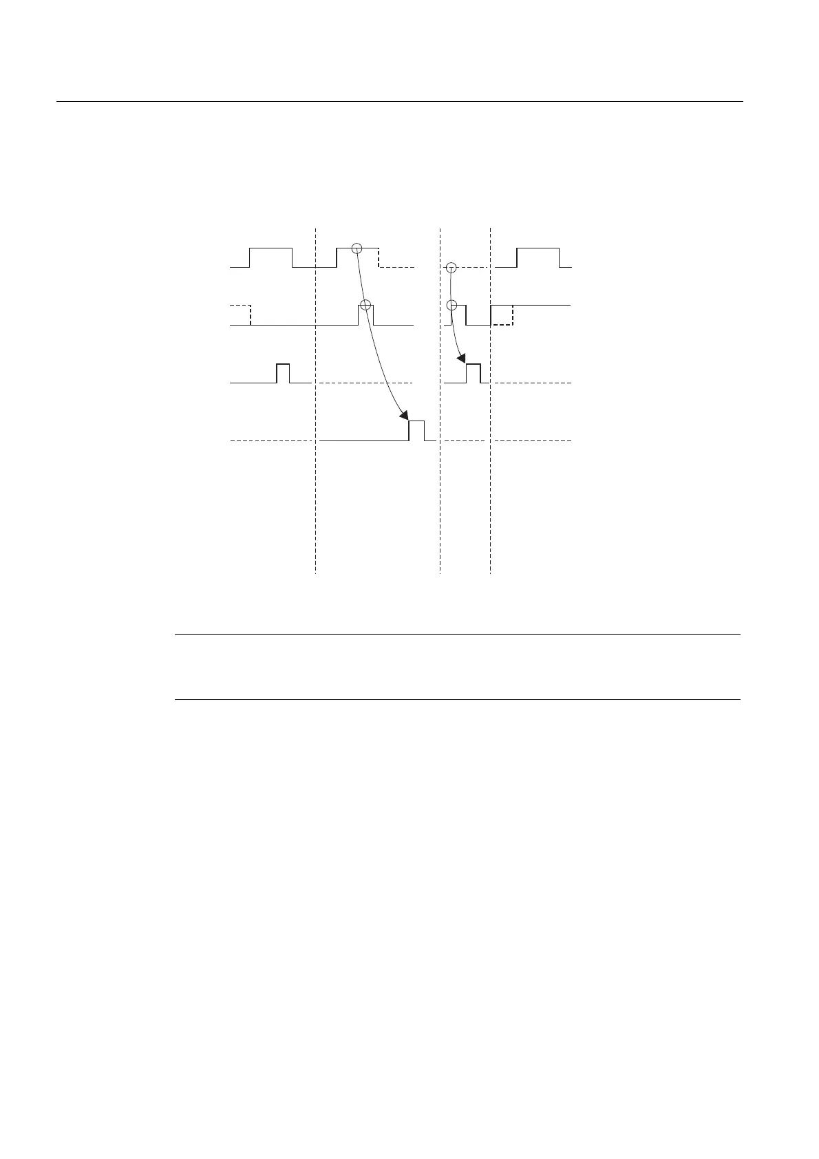
Time Sequence Chart for P_SEND (FB 3)
The figure below illustrates the behavior of the DONE and ERROR parameters, depending
on how the REQ and R inputs are wired.
5(4
5
'21(
(5525
6HQGLQJUHTXHVW
7HUPLQDWLRQZLWKRXWHUURU
7UDQVIHU5(6(7
7UDQVIHU5(6(7
7HUPLQDWLRQZLWKRXWHUURU
5HTXHVWLV
QRWH[HFXWHG
6HQGLQJLV
WXUQHGRII
7HUPLQDWLRQZLWKHUURU
VWQWK6(1'SDUW
Figure 6-1 Time Sequence Chart for P_SEND (FB 3)
Note
The REQ input is edge-triggered. A positive edge at the REQ input is sufficient. The result of
the logic operation must not be at "1" at any point during transfer.