Communication using function blocks
6.4 Using function blocks for the output of message texts to a printer
PtP coupling and configuration of CP 340
Manual, 04/2011, A5E00369892-03
117
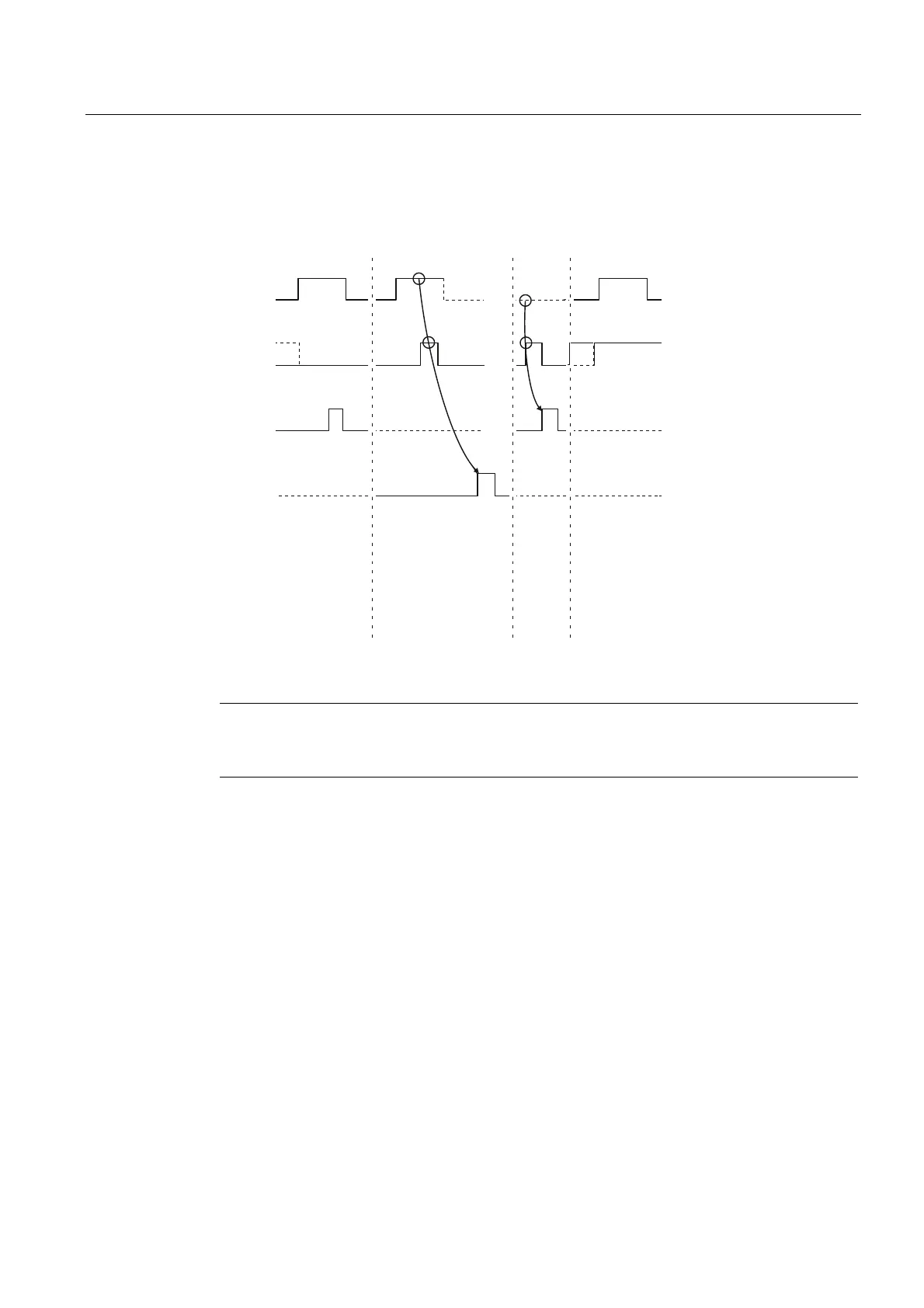
Time Sequence Chart for FB 4 P_PRINT
The figure below illustrates the behavior of the DONE and ERROR parameters, depending
on how the REQ and R inputs are wired.
6HQGLQJUHTXHVW
&RPSOHWLRQZLWKRXW
HUURUV
VWQWK35,17SDUW
5(6(7WUDQVPLWWHG
&RPSOHWLRQZLWKHUURUV
5(6(7WUDQVPLWWHG
&RPSOHWLRQZLWKRXW
HUURUV
35,17UHTXHVWLV
QRWH[HFXWHG
VHQGLQJLV
GLVDEOHG
5(4
5
'21(
(5525
Figure 6-4 Time Sequence Chart for FB 4 P_PRINT
Note
The REQ input is edge-triggered. A positive edge at the REQ input is sufficient. It does not
have to have a signal state of "1" during the entire transmission operation.