Communication using function blocks
6.5 Use of function blocks for reading and controlling the RS 2332C secondary signals
PtP coupling and configuration of CP 340
120 Manual, 04/2011, A5E00369892-03
Setting/resetting interface outputs of the CP 340
The user can set or reset the interface outputs via the corresponding parameter inputs of the
V24_SET FC. The V24_SET FC is called in the cycle or alternatively in a time-controlled
program statically (without conditions).
The binary result is not affected. The function does not issue error messages.
The LADDR parameter defines the CP 340 to be addressed.
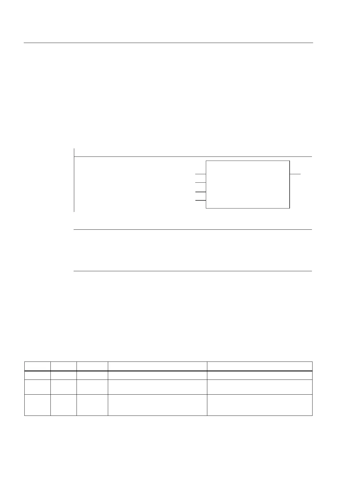
Block call
STL representation LAD representation
CALL V24_SET
LADDR: =
RTS: =
DTR: =
(1 (12
/$''5
576
'75
9B6(7
Note
The EN and ENO parameters are only present in the graphical representation (LAD or FBD).
To process these parameters, the compiler uses the binary result. The binary result is set to
signal state "1" if the block was terminated without errors. If there was an error, the binary
result is set to "0".
Assignment in the data area
The V24_SET function does not occupy any data areas.
V24_SET (FC 6) parameters
The table below lists the parameters of the V24_SET function (FC 6).
Table 6- 6 V24_SET (FC 6) parameters
Name Type Data type Comment Permitted values, remark
LADDR INPUT INT CP 340 base address The base address is taken from STEP 7.
RTS INPUT BOOL Request to send,
CP 340 ready to send
(Control CP 340 output)
DTR INPUT BOOL Data terminal ready,
CP 340 ready (see Chapter "RS 232C
accompanying signals (Page 46)")
(Control CP 340
output)