Communication using function blocks
6.6 Delete receive buffer, FB12 "P_RESET"
PtP coupling and configuration of CP 340
Manual, 04/2011, A5E00369892-03
123
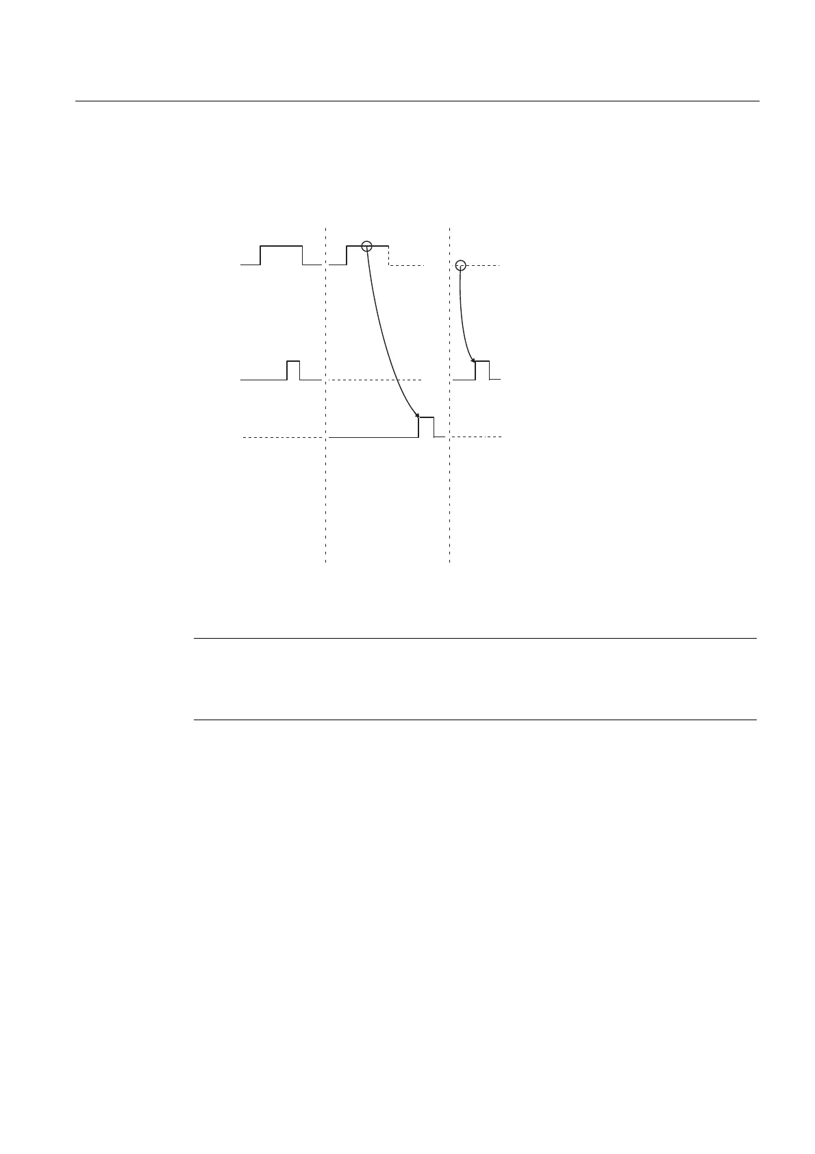
Time sequence chart for the P_RESET FB
The figure below illustrates the behavior of the DONE and ERROR parameters depending
on the input circuit of REQ.
5(4
'21(
(5525
'HOHWHUHFHLYHEXIIHU
7HUPLQDWLRQZLWKRXWHUURU
5(6(7WUDQVIHUUHG
7HUPLQDWLRQZLWKHUURU
5(6(7WUDQVIHUUHG
7HUPLQDWLRQZLWKRXWHUURU
Figure 6-5 Time sequence chart for the P_RESET FB
Note
The REQ input is edge-triggered. A positive edge at the REQ input is adequate. It is not
required that the RLO (result of logical operation) is "1" during the whole transmission
procedure.