Product Description
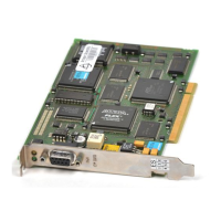
1.3 Design of the CP 340
PtP coupling and configuration of CP 340
Manual, 04/2011, A5E00369892-03
17
LED display elements
The following LED display elements are located on the front panel of the communication
processor:
SF
(red) Error display
TxD
(green) Interface sending
RxD
(green) Interface receiving
Section "Diagnosis via the Display Elem
ents of the CP 340 (Page 133)" descri
bes the
operating states and errors that these LEDs indicate.
Integrated interface
The CP 340 is available in three variants with different interface types:
● RS 232C
● X27 (RS 422/485)
● 20mA-TTY
The interface types are indicated on the front of the CP 340. A detailed interface description
can be found in Section "Properties of the serial interface (Page 18)".
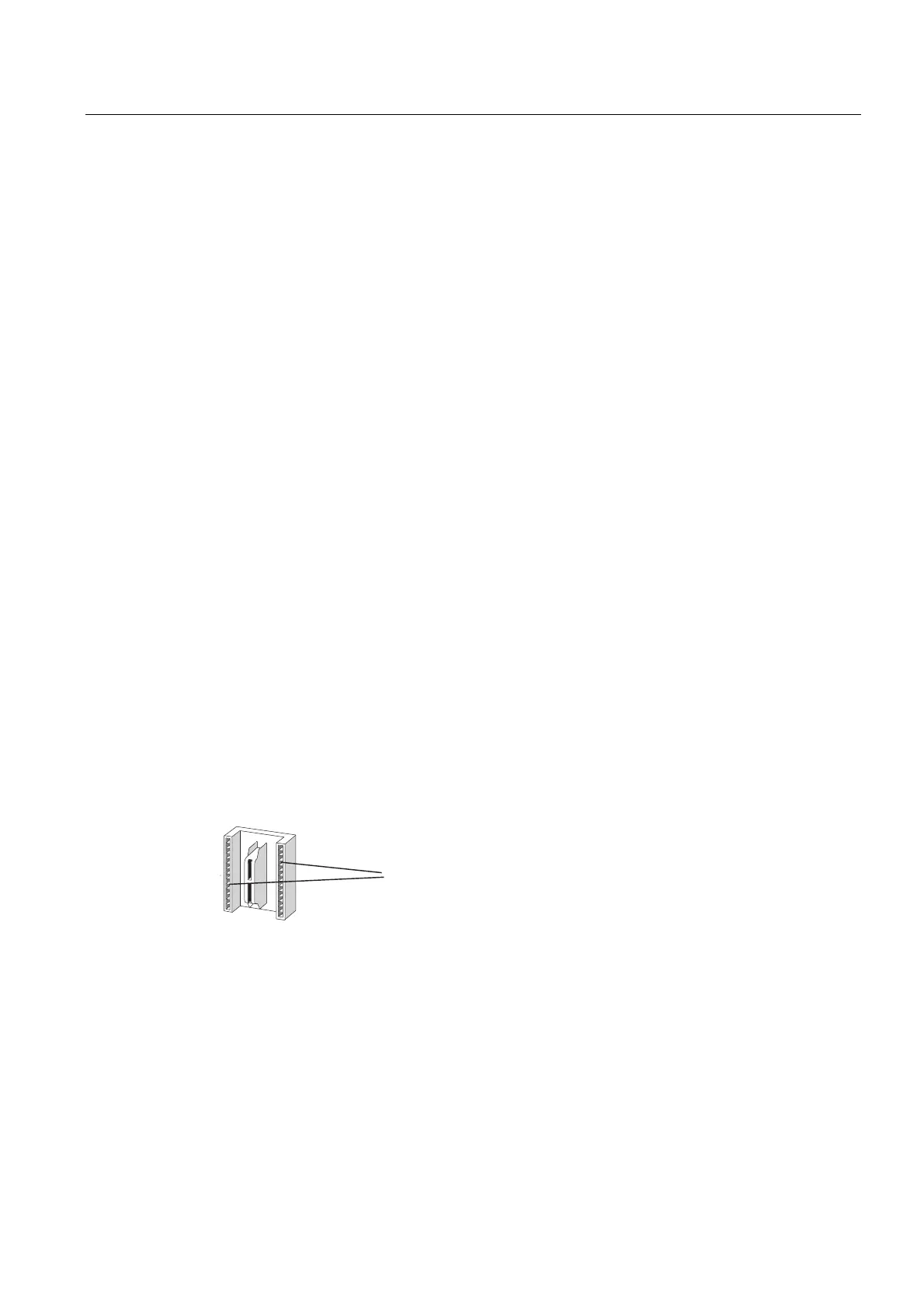
Bus connector for the S7 rear panel bus
A bus connector is supplied with the CP 340. The bus connector is plugged onto the back
panel of the CP 340 when it is mounted. The S7-300 rear panel bus is connected via the bus
connector.
The S7-300 rear panel bus is a serial data bus via which the CP 340 communicates with the
modules of the programmable controller and is supplied with the necessary voltage.
&RQWDFWVWRFRQQHFWLRQRIWKH
6%DFNSODQHEXV
Figure 1-2 Connector S7