Mounting and connection
4.2 Mounting and connecting the OP 73micro
OP 73micro, TP 177micro (WinCC flexible)
Operating Instructions, 09/2007, 6AV6691-1DF01-0AB0
43
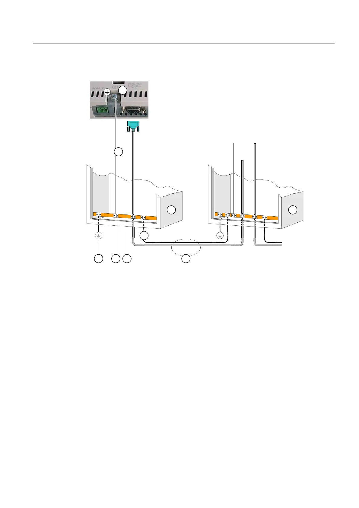
Wiring diagram
1
3 3
87
2
65
4
Figure 4-3 Installing the equipotential circuit
① Chassis ground terminal on the HMI device (example)
② Equipotential bonding conductor cross-section: 4 mm
2
③ Cabinet
④ Equipotential bonding conductor cross-section: min. 16 mm
2
⑤ Ground terminal
⑥ Cable clamp
⑦ Voltage bus
⑧ Parallel routing of the equipotential bonding conductor and data cable
See also
Electromagnetic compatibility (Page 23)
 Loading...


