Mounting and connection
4.2 Mounting and connecting the OP 73micro
OP 73micro, TP 177micro (WinCC flexible)
Operating Instructions, 09/2007, 6AV6691-1DF01-0AB0
45
See also
Interfaces (Page 41)
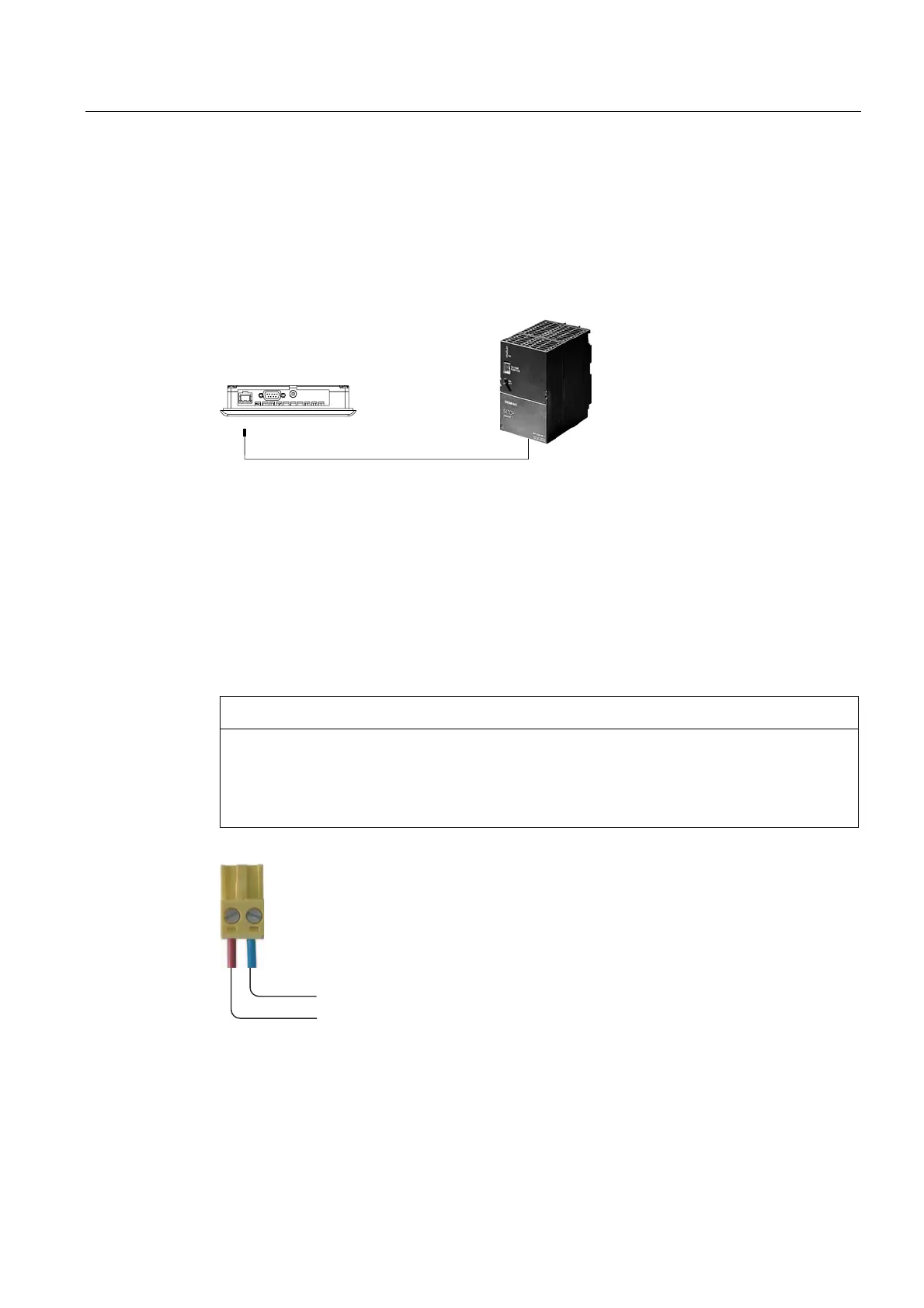
Wiring diagram
The figure below illustrates the connection between the power supply and the HMI device.
Figure 4-6 Connecting the power supply
The interfaces are described in the Specifications section.
Note when connecting
The power terminal block is included in the assembly kit and is designed for conductors with
a maximum cross-section of 1.5 mm
2
..
Connecting the terminal block
NOTICE
Damage
Pressure on the screwdriver may damage the HMI device socket if the terminal block is
plugged in when you tighten the screws.
Always remove the terminal block to connect the wires.
*1'
DC +24 V
Figure 4-7 Connecting the terminal block
Connect the power supply cables to the terminal block as shown in the figure above. Ensure
that the cables are not crossed. Refer to the label showing the pin-out on the rear of the HMI
device.