13-2
Equipment
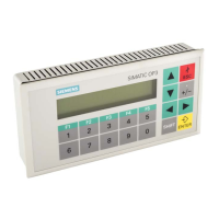
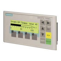
Manual OP7, OP17
Release 04/99
With
pressing a function key, it can be used to set a bit on the PLC, where it
is evaluated by the application program.
For this, you must have created the necessary data area on the PLC for the
keyboard image and have specified the appropriate area pointer in the confi
-
guration for assigning the key to a bit.
At most, the activation of two simultaneously pressed keys can be
transferred.
A bit is permanently assigned to every key on the system key board – apart
from the arrow keys – in the data area for system keyboard bits. The bit re
-
mains set for as long as the corresponding key is pressed. The bit is reset
when you release the key
.
Owing to the evaluation of this data area, the operator
’
s attention can be
drawn to the wrong operation of a key – for example, by means of an error
message.
T
ransfer of date and time can be initiated from the OP by means of a PLC job
in order to synchronize the OP and PLC.
By creating a suitable data area, it is possible for alarm messages to be
acknowledged by the PLC instead of on the OP
.
If the PLC is required to announce that an alarm message has been
acknowledged, this can be done following creation of a suitable data area.
Function
keyboard
image
System keyboard
image
Date and time
PLC
OP
acknowledgment
area
OP
PLC
acknowledgment
area
 Loading...
