14-4
Equipment
Manual OP7, OP17
Release 04/99
14.2.1 Connecting the Power Supply
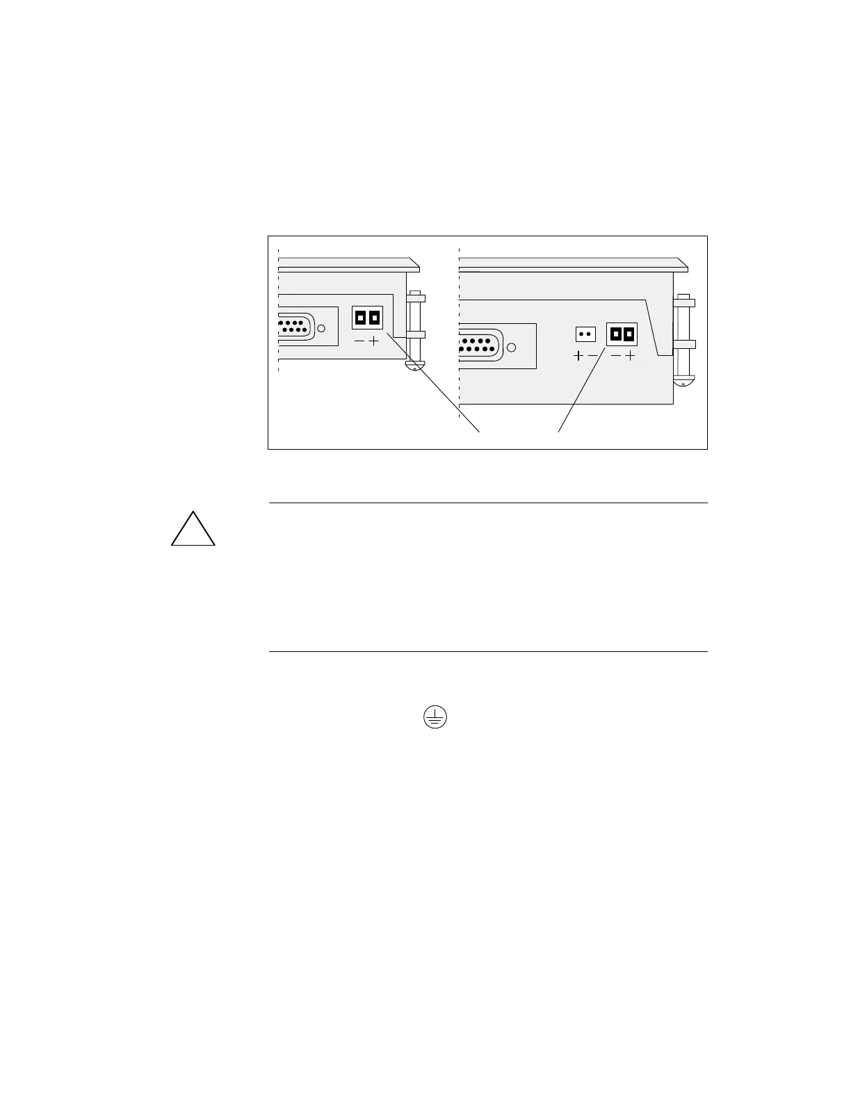
There
is a two-pin screw-type terminal on the lower side of the OP housing
for connecting the power supply. The screw-type terminal is designed for
cables having a cross-section not lar
ger than 2.5 mm
2
. The terminal screws
are accessible via drill holes in the rear panel.
figure 14-1 shows the location of the screw-type terminals on the OP7 and
OP17.
OP7 OP17
terminal block
Figure 14-1 Connecting the Power Supply (View of Underside of OP)
!
Caution
With
a 24 V supply
, make sure the extra-low voltage is isolated safely
.
Use only power supplies complying with ICE 364-4-41 or HD 384.04.41
(DE 0100. Part 410).
The voltage supply must be within the permissible voltage range for the
device in question (see chapter C), otherwise it is not possible to exclude
the possibility of failures.
Connect the chassis ground
on the bottom of the device to the cabinet
ground.
Terminal
Block
Chassis ground
 Loading...


