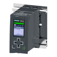
3.5.2 Front view of the CPU without front flaps
The figure below shows the operator controls and connection elements of the
CPU1517H‑3PN.
① Mode selector
② No function
③ LED displays for the ports of the X3 and X4 interfaces
④ MAC addresses of the X3 and X4 interfaces
⑤ H-Sync X3 and X4 interfaces with 1 port each (not visible in graphic)
⑥ Fixing screws
⑦ Connector for power supply
⑧ PROFINETIO interface X2 with 1 port
⑨ PROFINETIO interface X1 with 2 ports
⑩ MAC addresses of the X1 and X2 interfaces
⑪ LED displays for the ports of the X1 and X2 interfaces
⑫ Slot for the SIMATIC memory card
⑬ Display connector
⑭ LEDs for the current operating state and diagnostic status of the CPU
Figure 3-5View of the CPU1517H‑3PN (without front panels) - front
22
CPU1517H-3PN (6ES7517-3HP00-0AB0)
Equipment Manual, 11/2022, A5E42011886-AD
Product overview
3.5 Operator controls and display elements

 Loading...


