3.5.4 Bottom view
Interfaces and synchronization modules
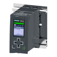
The figure below shows the position of the interfaces on the underside of the CPU.
① PROFINETIO interface X1 with 2 ports
② PROFINETIO interface X2 with 1 port
③ H-Sync interface X3 (H-Sync channel 1) without synchronization module
④ H-Sync interface X4 (H-Sync channel 2) without synchronization module
Figure 3-7Bottom view
3.6 Mode selector
You use the mode selector to:
•
Request a change to a specific operating state
•
Disable or enable the change of a specific operating state
(if, for example, the mode selector is set to STOP, you cannot switch the CPU to RUN via a
communication task configured in the TIA Portal or via the display)
The following table shows the position of the switch and the corresponding meaning.
Table 3-1Mode switch settings
Position Meaning Explanation
RUN RUN operating state The CPU has permission to go to RUN.
STOP STOP operating state The CPU does not have permission to go to RUN.
MRES Memory reset Position for CPU memory reset.
24
CPU1517H-3PN (6ES7517-3HP00-0AB0)
Equipment Manual, 11/2022, A5E42011886-AD
Product overview
3.6 Mode selector

 Loading...


