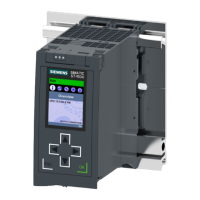
3.5.3 Rear view of the CPU
The figure below shows the connection elements on the rear of the CPU1517H‑3PN.
① Shield contact surfaces
② Fixing screws
Figure 3-6View of the CPU1517H‑3PN - rear
23
Product overview
3.5 Operator controls and display elements
CPU1517H-3PN (6ES7517-3HP00-0AB0)
Equipment Manual, 11/2022, A5E42011886-AD

 Loading...


