3. Avoid using a hammer.
4. Secure the parallel key from falling out or remove it.
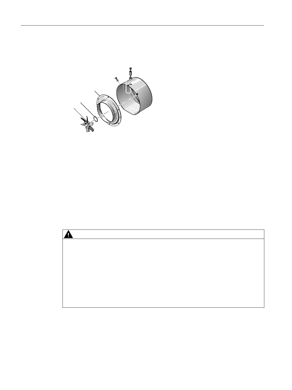
Figure 9-1 Ventilation (schematic diagram with axial fan)
Assembly
1. Remove the parallel key lock or insert it in the keyway.
2. Check the correct seating.
3. Then push the external fan ① onto the shaft up to its stop. Use a suitable device for this
purpose.
4. Insert the retaining ring ② into the corresponding groove and check its fit.
Air inlet nozzle
Two-pole machines are equipped with an air inlet nozzle ③. The spacing between external fan
and air inlet nozzle must measure ≥ 2 mm evenly over the circumference.
WARNING
Danger of explosion as a result of a fan impeller coming into contact with its surroundings
The fan impeller of a metallic external fan coming into contact with another component can
cause arcing and explosion. This can result in death, serious injury or material damage.
● Remove any dirt.
● Regularly and after any performed work check the distance between the fan impeller and
adjacent components, such as air inlet nozzle. Correct the alignment of the components,
if necessary. The gap between the air inlet nozzle and the fan impeller should be at least
2 mm around the complete circumference.
● Please contact the Service Center if you require any support when aligning the
components.
Maintenance
9.3 Corrective maintenance
1MB5 SH 400/450
122 Operating Instructions, 05/2019, A5E45959221A



 To Next Page