Interfaces
3.6 Onboard measuring system interface (C230-2, C240)
SIMOTION C
Operating Instructions, 02/2012
53
Connector pin assignment
Designation:
X3, X4, X5, X6 - ENCODER 1 to 4
Assignment of ENCODER - axis channel:
X3 - axis channel 1
X4 - axis channel 2
X5 - axis channel 3
X6 - axis channel 4
Type: 15-pin Sub-D socket connector
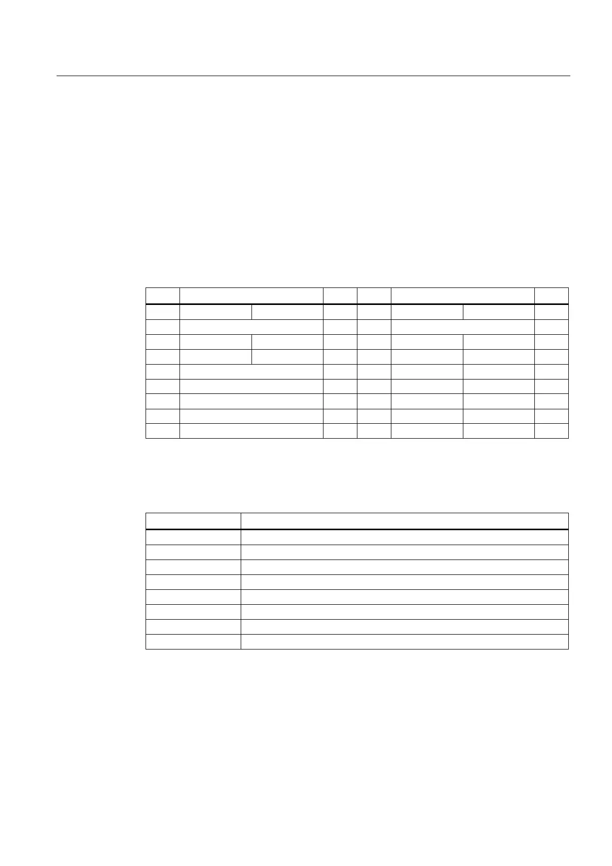
Table 3- 9 Assignment of connectors X3 to X6
Pin Encoder Type Pin Encoder Type
Incremental Absolute Incremental Absolute
1 Not assigned 9 MEXT VO
2 CLS O 10 Z I
3 CLS_N O 11 Z_N I
4 P5EXT VO 12 B_N I
5 P24EXT VO 13 B I
6 P5EXT VO 14 A_N DATA_N I
7 MEXT VO 15 A DATA I
8 Not assigned
Signal names
Table 3- 10 Measuring system interface signal names
Signal name Meaning
A, A_N Track A non-inverted and inverted (incremental encoder)
B, B_N Track B non-inverted and inverted (incremental encoder)
Z, Z_N Zero mark non-inverted and inverted (incremental encoder)
CLS, CLS_N SSI clock shift non-inverted and inverted (absolute encoder)
DATA, DATA_N SSI data non-inverted and inverted (absolute encoder)
P5EXT +5 V supply
P24EXT +24 V supply
MEXT Supply ground
Signal type
VO - voltage output (supply)
O - output (5 V signal)
I - input (5 V signal)