Interfaces
3.8 I/O interface
SIMOTION C
Operating Instructions, 02/2012
71
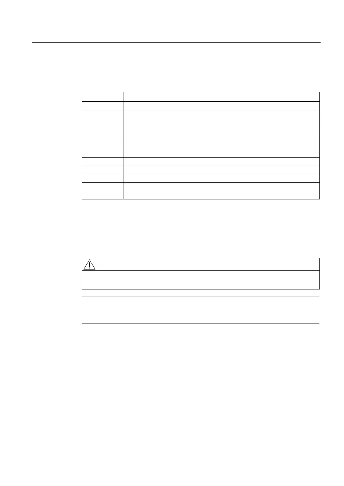
Signal names
Table 3- 18 Signal names of the I/O interface
Signal name Meaning
RDY.1 to 2 Ready (READY contact 1 to 2)
B1 to B4
Inputs B1 to B4 for external zero mark signals (C230-2/C240) or
Measuring pulse inputs B1 to B4 for global measuring (C240/C240 PN) or
Digital inputs B1 to B4
M1, M2
Measuring pulse inputs M1 and M2 for local measuring (C230-2/C240) or
Digital inputs M1 and M2
I0 to I11 Digital inputs 0 to 11
Q0 to Q7 Digital outputs 0 to 7
L+ Supply for digital outputs
M
output
Reference potential for digital outputs
M
input
Reference potential for digital inputs
Signal type
DI - digital input (24 V signal)
DO - digital output (24 V signal)
K - switching contact
VI - voltage input
DANGER
The 24 V power supply is to be designed as functional extra-low voltage with protective
separation in accordance with EN60204-1, Section 6.4, PELV (with G ground).
Note
The connecting cable between the voltage source and the load current supply connector L+
and the associated reference potential M should not exceed a maximum length of 10 m.