Procedure
1.
Remove the spacers (screws: M3, Torx T10).
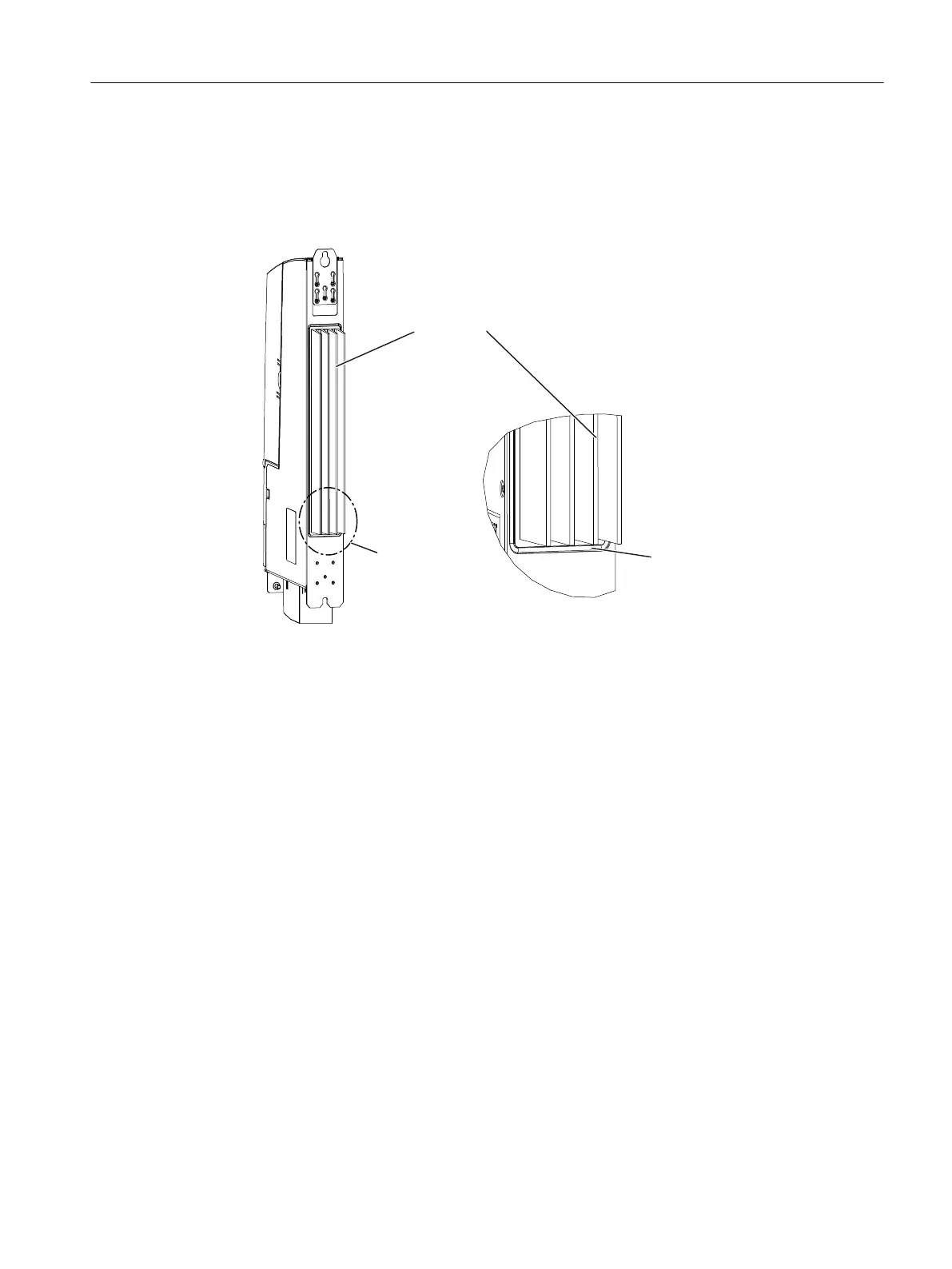
2. Fit the seal around the cooling fins of the Control Unit.
,QVHUWVHDOIRUH[WHUQDOFRROLQJ
)&$$$$LQWKH
JURRYHRQWKHKHDWVLQN
'HWDLO$
'HWDLO$
Figure 3-5 Mounting the seal
3. Loosen
the three M3 screws (screws: M3, Torx T10) on the upper clip and push the clip up
until the upper hole protrudes beyond the housing.
4. Tighten up the three screws on the clip again (0.8 Nm tightening torque).
5. Push the Control Unit with the heat sink through the panel cutout.
6. Fasten the Control Unit directly on the rear wall of the control cabinet with an M6 screw at
the top and bottom, tightening torque: 6 Nm (see ① in the "Panel cutout" figure).
3.2.5 Fixing elements
The Controller Extension CX32‑2 and the Control Unit CU320‑2 can be mounted on the side
wall of a SINAMICS S120 Line Module. The mounting elements required for this are included
with the SINAMICS S120 Line Module and can be plugged if necessary.
● CU320-2: 3 mounting elements required
● CX32-2: 5 mounting elements required
Installing
3.2 Installing the SIMOTION D4x5-2
SIMOTION D4x5-2
Commissioning and Hardware Installation Manual, 03/2018, A5E33441636B 41
 Loading...


