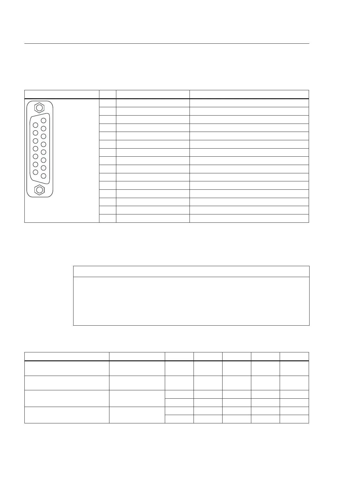
Interface assignments
Table 4-13
Interface assignment X23
Representation Pin Name Description
1 +Temp KTY or PTC input
2 SSI_CLK SSI clock positive
3 SSI_XCLK SSI clock negative
4 P_Encoder 5 V / 24 V Encoder power supply
5 P_Encoder 5 V / 24 V Encoder power supply
6 P_Sense Sense input encoder power supply
7 G_Encoder (G) Ground for sensor power supply
8 -Temp (G) Ground for KTY or PTC
9 G_Sense (G) Ground sense input
10 RP R track positive
11 RN R track negative
12 BN B track negative
13 BP B track positive
14 AN_SSI_XDAT A track negative / SSI data negative
15 AP_SSI_DAT A track positive / SSI data positive
For Pin 1 / Pin 8: The associated temperature channel (T1) can be assigned parameters as an individual channel or together
in combination with the second temperature channel (T2) at interface X120.
(For parameterization, see the
SINAMICS S120 Commissioning Manual
).
For Pin 6 / Pin 9: At an encoder supply of 5 V, the voltage drops on the encoder supply cables are recorded and compensated
by means of the sense cables. For this purpose, the encoder supply is adjusted to the SIMOTION D410.
NOTICE
Motor overheating due to an incorrectly connected KTY temperature sensor
A sensor connected with the incorrect polarity cannot detect the motor overheating.
Connect the KTY temperature sensor with the correct polarity.
For
more information on the temperature sensors and how to use them, see the
SINAMICS
S120
Commissioning Manual, in Chapter Temperature sensors for SINAMICS components.
Table 4-14 Specification of measuring systems that can be connected
Parameter Designation Threshold Min. Type Max. Unit
High signal level
(TTL bipolar at X23)
1)
U
Hdiff
2 5 V
Low signal level
(TTL bipolar at X23)
1)
U
Ldiff
-5 -2 V
High signal level
(HTL unipolar)
U
H
High 17 V
CC
V
Low 10 V
CC
V
Low signal level
(HTL unipolar)
U
L
High 0 7 V
Low 0 2 V
Interfaces
4.6 Encoder interface (HTL/TTL/SSI)
SIMOTION D410
54 Manual, 04/2014
 Loading...


