Installation 06.2006
6SE7087-6KP50 Siemens AG
5-8 Operating Instructions SIMOVERT MASTERDRIVES
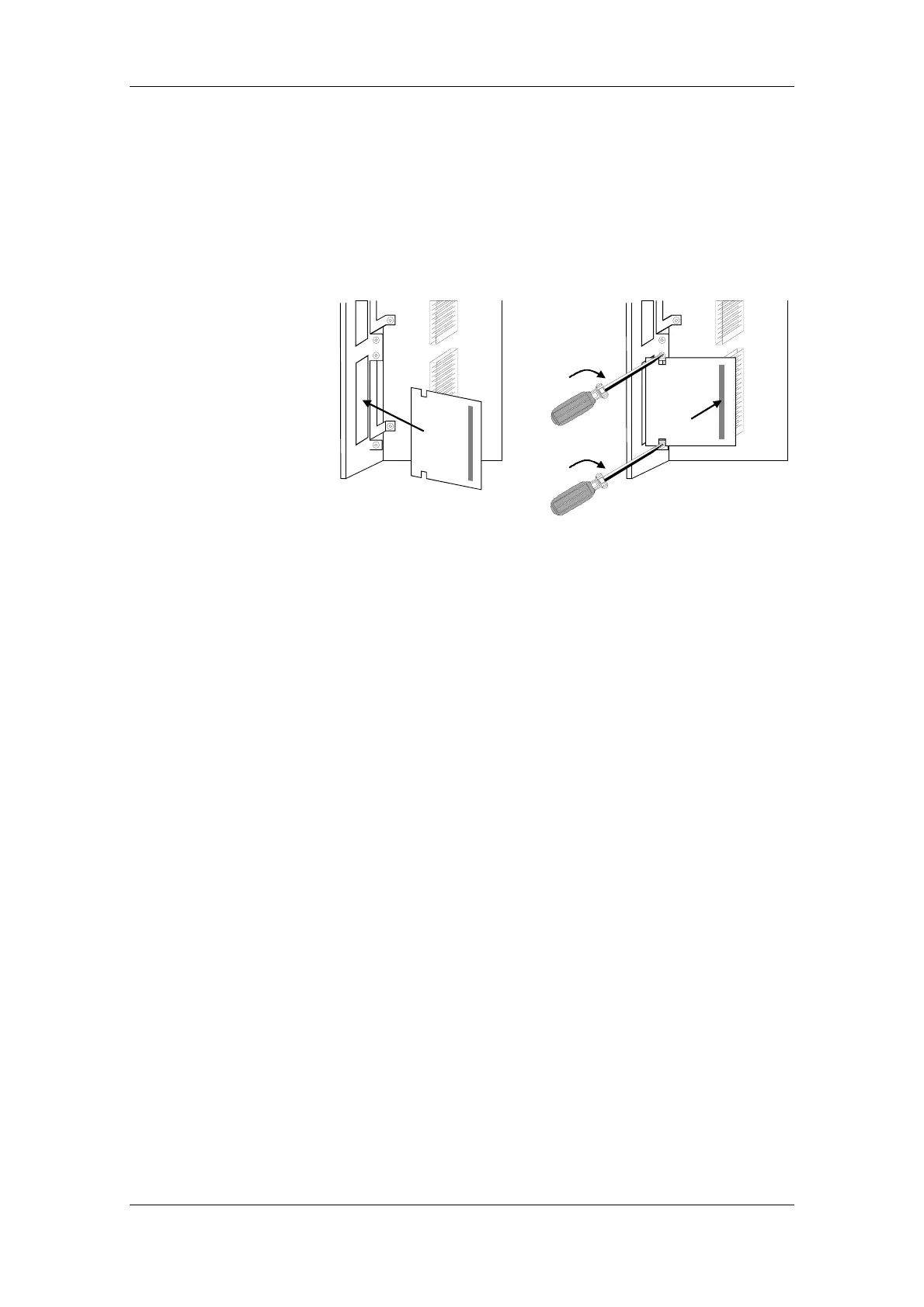
♦ Insert the optional board from the behind the broken-out slot cover
(
c) until the position of the 64-pole system connector on the
electronic board corresponds with the position of the socket.
♦ Insert the option board into the 64-pole system connector on the
electronic board (
d).
♦ Screw the optional board tight at the fastening points in the front
section of the optional board with the two screws (
e).
Slot C
c
Slot C
d
e
e
Fig. 5-7 Installing the optional board
♦ Keep the front of the unit tilted about approximately 30 ° forwards
and insert the cutout of the lower guide plate - approaching from
below - into the strip on the power section.
♦ Insert the connection cable plug into the power section socket and
close the locking lever.
♦ Carefully return the front of the unit into the housing. Make sure that
the guide plates on the right-hand side of the front (viewed from the
front) enter the housing cutouts.
♦ Screw the front of the unit securely to the power section with the two
fixing screws.
♦ Re-connect all previously removed connecting cables.
♦ Check all connecting cables and the shield to make sure they sit
properly and are in the correct position.
♦ To designate the optional board, insert the relevant designation
plate into the envisaged position on the front of the unit.
♦ After powering up the voltage, you can log on the optional boards in
the software of the unit and commence start-up.
Mounting the
optional board
Assembling and
mounting the unit
Connecting up the
unit
Designating the
optional board