06.2006 Connecting-up
Siemens AG 6SE7087-6KP50
SIMOVERT MASTERDRIVES Operating Instructions 7-7
7.1.2 Power connections for units with a width of 135 mm and 180 mm
The DC link bus module serves to supply the unit with electrical energy.
Bar Designation Meaning Range
3 PE3 Protective conductor connection
2 D / L- DC link voltage - DC 510 - 650 V
1 C / L+ DC link voltage + DC 510 - 650 V
Connectable cross-section: "Electro-plated copper" 3x10 mm, rounded
off according to DIN 46433
Bar 1 is at the front when installed.
Table 7-3 DC link busbars
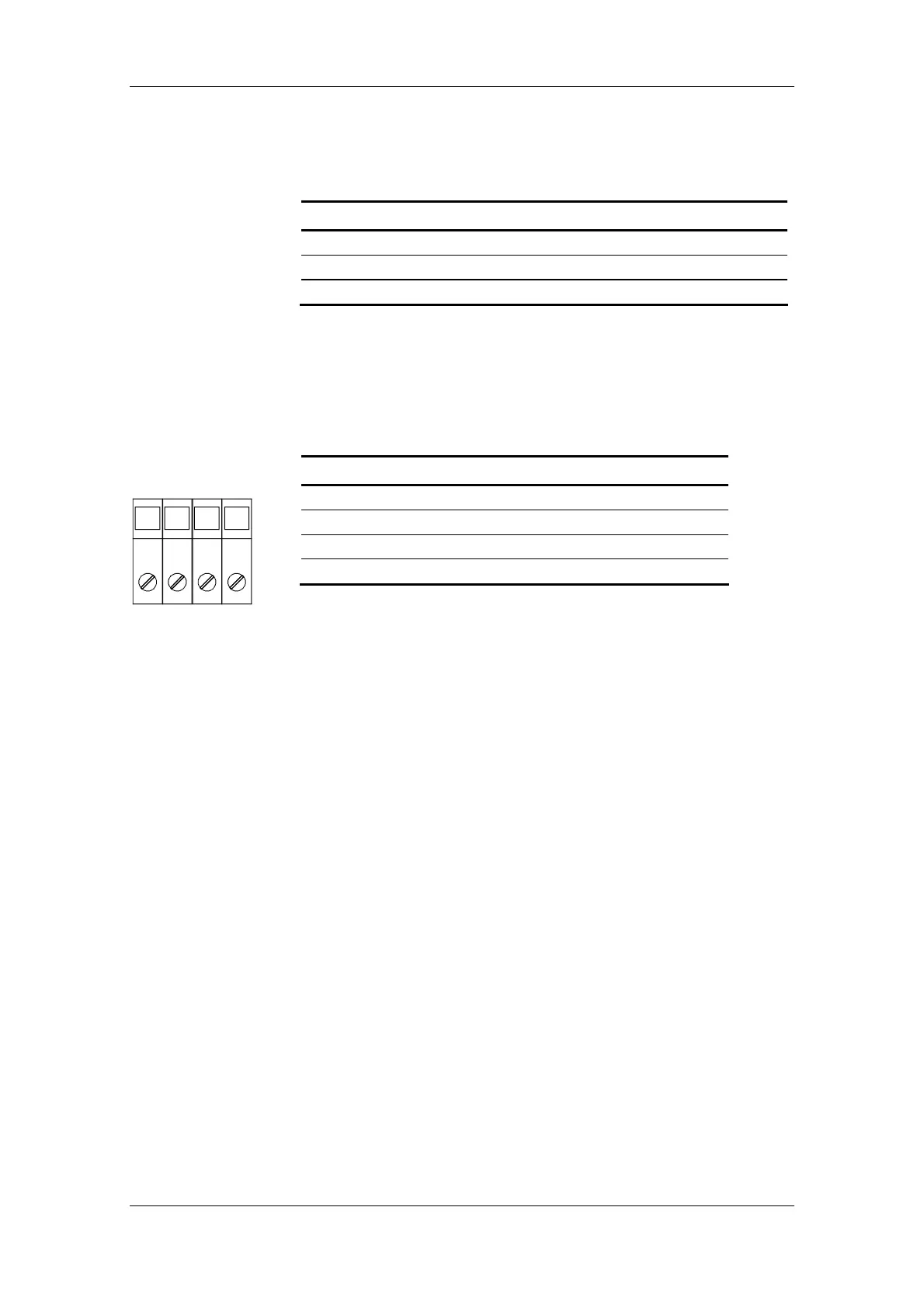
The motor connection is to a terminal block at the bottom of the unit.
Terminal Meaning Range
PE Protective conductor connection
U2 / T1 Phase U2 / T1 3AC 0 V - 480 V
V2 / T2 Phase V2 / T2 3AC 0 V - 480 V
W2 / T3 Phase W2 / T3 3AC 0 V - 480 V
Connectable cross-section:
Housing width 135 mm: 10 mm² (AWG 8), stranded
Housing width 180 mm: 16 mm² (AWG 6), stranded
Viewed from the front, Terminal PE is at the left.
Table 7-4 Motor connection
The motor cables must be dimensioned in accordance with VDE 298,
Part 2.
After installation of the connector, the shield of the motor cable must be
fixed to the shield plate through a large surface area.
X3 - DC link bus
module
X2 – Motor
connection
≤ 18.5 kW
PE U2 V2 W2